00193922-01.pdf - 第145页
User Manual SIPLAC E HF Series 4 Setting up and commissioning Software Version SR.505.xx 05/2004 US Edition 4.2 Dimensions of the placement systems 145 4.2.1 M achine foot clearances 4 Fig. 4.2 - 4 Machine foot c learanc…
4 Setting up and commissioning User Manual SIPLACE HF Series
4.2 Dimensions of the placement systems Software Version SR.505.xx 05/2004 US Edition
144
4
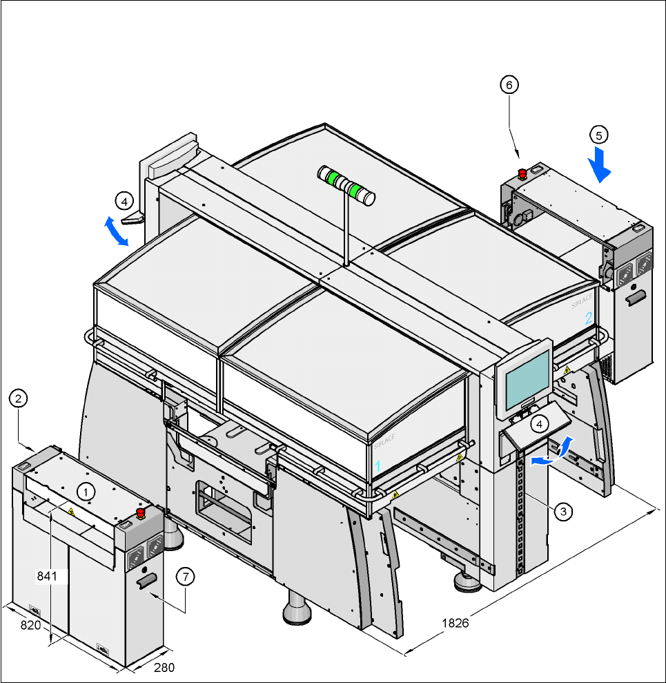
Fig. 4.2 - 3 Dimension of the machine in millimeters - Extension kits removed
(1) Extension kit on the PCB input side - removed for delivery
(2) Computer unit, in extension kit (1)
(3) Pneumatic unit, behind the cover
(4) Fold-down keyboards
(5) Extension kit on the PCB output side - may be removed if necessary
(6) Axis unit, in extension kit (5) - HF: gantries 1 and 3, HF/3: gantry 3
(7) Axis unit, in extension kit (1) - HF/3: gantries 1 and 4
User Manual SIPLACE HF Series 4 Setting up and commissioning
Software Version SR.505.xx 05/2004 US Edition 4.2 Dimensions of the placement systems
145
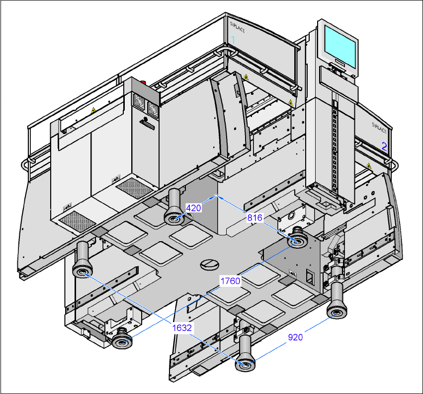
4.2.1 Machine foot clearances
4
Fig. 4.2 - 4 Machine foot clearances in millimeters
4 Setting up and commissioning User Manual SIPLACE HF Series
4.2 Dimensions of the placement systems Software Version SR.505.xx 05/2004 US Edition
146
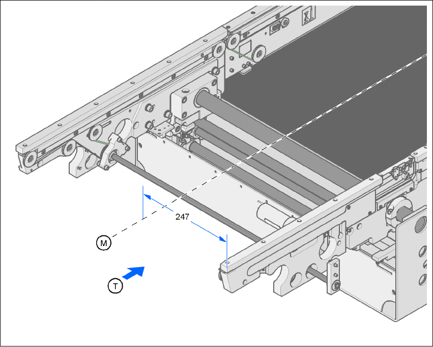
4.2.2 Distance between right-hand side of PCB conveyor and the machine center
4.2.2.1 Single conveyor
4
Fig. 4.2 - 5 Distance between the right-hand side of the PCB conveyor and the machine center in millimeters
(single conveyor)
4
M Machine center
T Direction of PCB transport