00193922-01.pdf - 第167页
User Manual SIPLAC E HF Series 4 Setting up and commissioning Software Version SR.505.xx 05/2004 US Edition 4. 5 Setting up the placement machine 167 4.5.4.1 Presetting the height of the "HS50" machine feet The…
4 Setting up and commissioning User Manual SIPLACE HF Series
4.5 Setting up the placement machine Software Version SR.505.xx 05/2004 US Edition
166
4
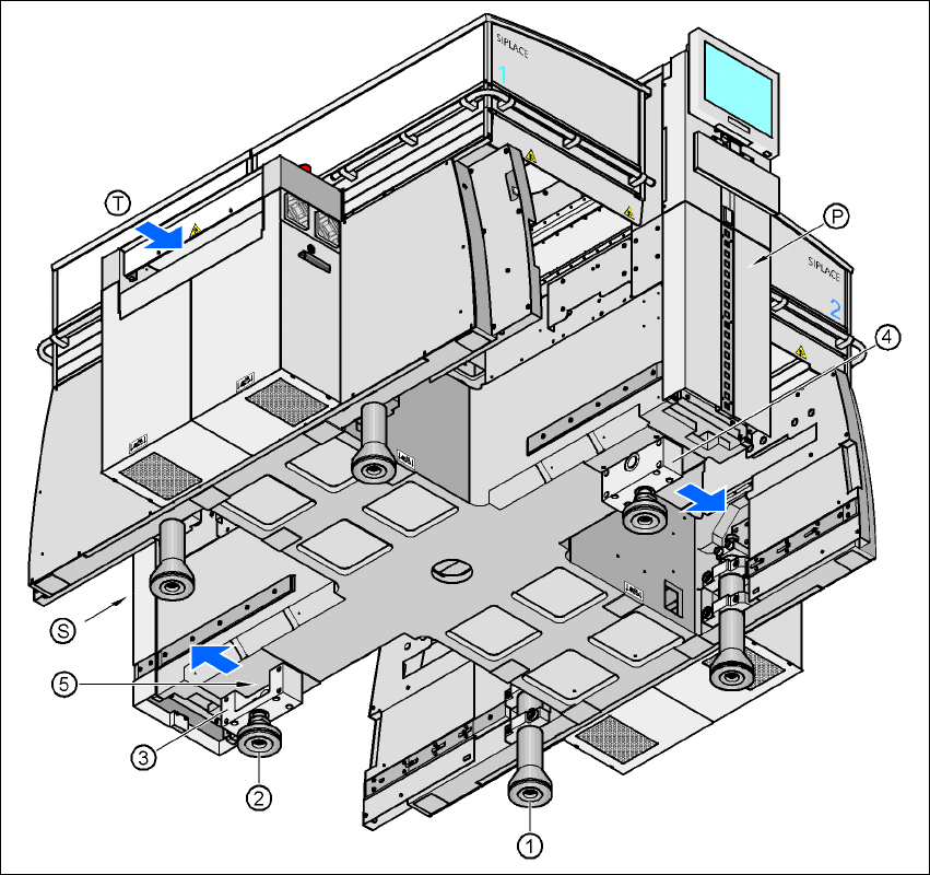
Fig. 4.5 - 2 Placement machine feet
4
(1) Machine foot
(2) "HS50" machine foot
(3) Spacer on the pneumatic unit side
(4) Spacer on the power supply unit side
(5) Threaded hole for the "HS50" machine foot
(T) Direction of PCB transport
(P) Pneumatic unit
(S) Power supply unit
User Manual SIPLACE HF Series 4 Setting up and commissioning
Software Version SR.505.xx 05/2004 US Edition 4.5 Setting up the placement machine
167
4.5.4.1 Presetting the height of the "HS50" machine feet
The "HS50" machine feet are preset first. The spacer must be bolted to the underside in the cor-
rect position for the machine height.
Setting the PCB transport height to 830 mm 4
You will not need a spacer for a PCB transport height of 830 mm.
Æ Screw the "HS50" machine foot as far as possible into the thread provided (see point 5 in Fig.
4.5 - 2
).
Setting the PCB transport height to 900 mm 4
You will need the spacer for a PCB transport height of 900 mm.
Æ Align the spacer so that the 90 mm side is vertical and the hole for the "HS50" machine foot
points downwards.
4
4
4
4
4
4
4
4
4
4
4
4
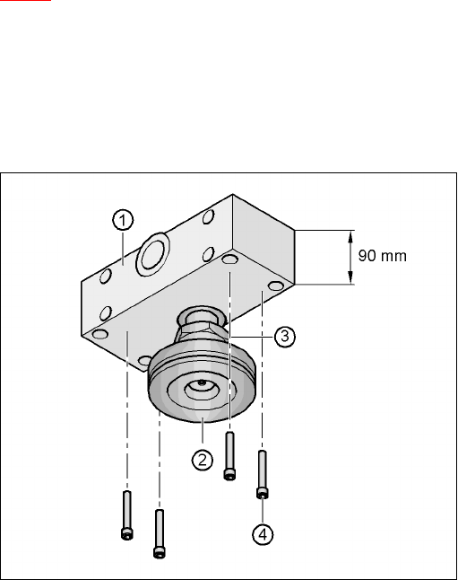
Fig. 4.5 - 3 Alignment of the spacer for a transport height of 900 mm
4
(1) Spacer height 90 mm
(2) "HS50" machine foot
(3) M24 lock nut
(4) Hexagon socket head screw M12x80, 4x
4 Setting up and commissioning User Manual SIPLACE HF Series
4.5 Setting up the placement machine Software Version SR.505.xx 05/2004 US Edition
168
Æ Screw the thread of the "HS50" machine foot into the hole on the underside of the spacer.
Æ Align the two spacers on the underside of the machine as follows:
– The opening in the spacer on the pneumatic unit side points in the direction of PCB trans-
port (see point 4 in Fig. 4.5 - 2
on page 166).
– The opening in the spacer on the power supply side points against the direction of PCB
transport (see point 3 in Fig. 4.5 - 2
on page 166).
Æ Fix each spacer using four hexagon socket head screws M12x80 (see point 4 in Fig. 4.5 - 3)
using the size 10 mm screwdriver bit.
Setting the PCB transport height to 930 mm and 950 mm 4
You will also need the spacer for PCB transport heights of 930 mm and 950 mm.
Æ Align the spacer so that the 122.5 mm side is vertical and the hole for the "HS50" machine foot
points downwards.
4
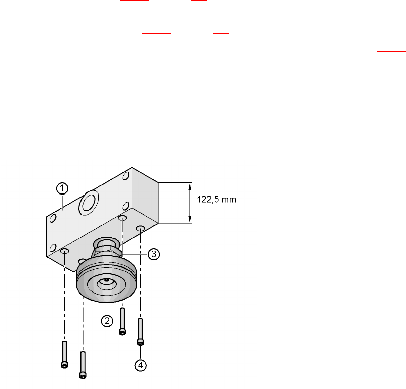
Fig. 4.5 - 4 Alignment of the spacer for transport heights of 930 and 950 mm
4
(1) Spacer height 122.5 mm
(2) "HS50" machine foot
(3) M24 lock nut
(4) Hexagon socket head screw M12x80, 4x