00193922-01.pdf - 第282页
7 Station extensions User Manual SIPLACE HF Series 7.1 Nozzle changer Software V ersion SR.505.xx 05/2004 US Edition 282 7.1.1.9 Assembly kit fo r the "row 2" nozzle cha nger The "row 2" nozzl e chang…
User Manual SIPLACE HF Series 7 Station extensions
Software Version SR.505.xx 05/2004 US Edition 7.1 Nozzle changer
281
PLEASE NOTE
Make sure that you insert the magazine so that the centering pins slide into the centering hole
(item 3) and slot (item 4). 7
Æ First place the side of the magazine with the numbered nozzles 1, 2, 3 and 4 on the base. The
retaining clamp (item 2) must slide into the slot in the magazine.
Æ Push the spring hook away from the magazine.
Æ Press the magazine so that it lies flat on the base, then release the spring hook. The spring
hook must latch into place.
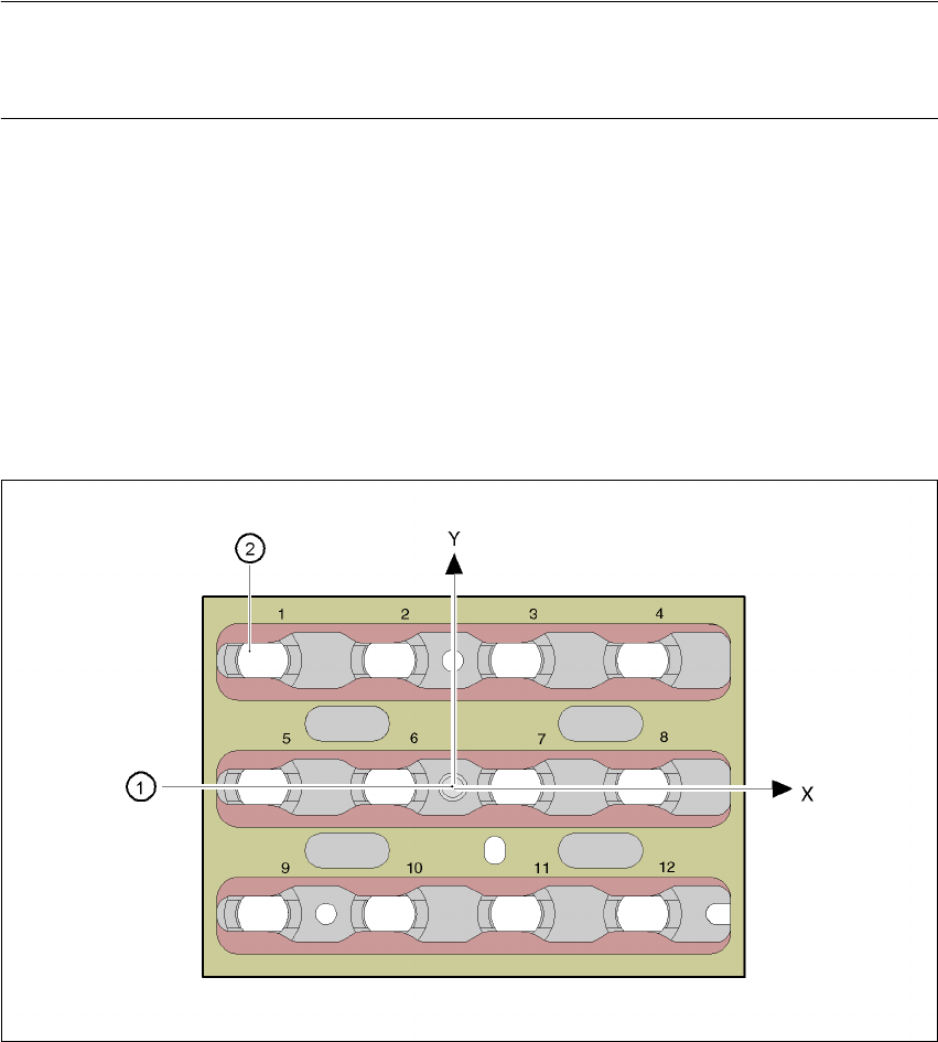
7.1.1.8 Position detection
Every magazine of the nozzle changer has a positioning fiducial for position detection.
7
Fig. 7.1 - 7 Nozzle changer - position detection
(1) Positioning fiducial
(2) Position of the nozzles in the magazine with respect to the positioning fiducial
7 Station extensions User Manual SIPLACE HF Series
7.1 Nozzle changer Software Version SR.505.xx 05/2004 US Edition
282
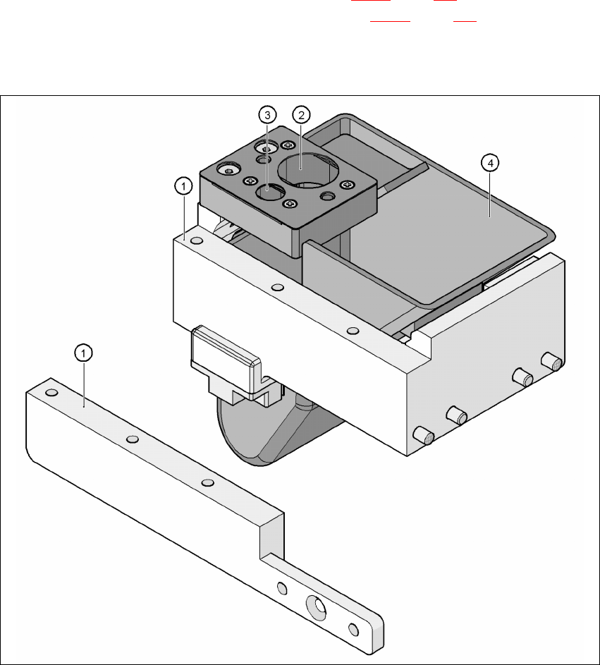
7.1.1.9 Assembly kit for the "row 2" nozzle changer
The "row 2" nozzle changer may be installed at the following locations:
HF placement machine: Locations 1 and 3 (see Fig. 7.1 - 2
, page 274)
HF/3 placement machine: Locations 1, 3, and 4 (see Fig. 7.1 - 3
, page 275)
The retrofit package contains an assembly kit and a nozzle take-off device with reject bin, in ad-
dition to the nozzle changer.
7
Fig. 7.1 - 8 Assembly kit for the "row 2" nozzle changer
(1) Assembly kit for the "row 2" nozzle changer
(2) Nozzle take-off device for type 8xx nozzles
(3) Nozzle take-off device for type 9xx nozzles
(4) Nozzle reject bin
User Manual SIPLACE HF Series 7 Station extensions
Software Version SR.505.xx 05/2004 US Edition 7.1 Nozzle changer
283
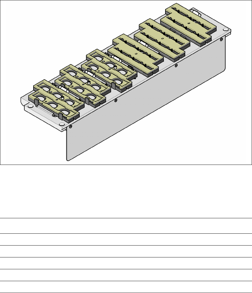
7.1.2 Nozzle changer for the 6-segment Collect&Place head
This nozzle changer can hold up to 6 magazines, each with 6 nozzle holders. There are two types
of magazine available: magazines for type 8xx nozzles and magazines for type 9xx nozzles. The
magazines are seated on a common support. They are centered using two parallel pins and fixed
in place with clips.
7
Fig. 7.1 - 9 Nozzle changer for the 6-segment Collect&Place head
7.1.2.1 Technical data
7
Nozzle changer for the 6-segment Collect&Place head
Dimensions (length x width x height) 448 x 122.5 x 97.7 mm³
Number of nozzle holders 6
Nozzle types 8 xx, 9 xx
Time required to open and close the locking plate < 200 ms
Compressed air connection 0.48 MPa (4.8 bar)