00193922-01.pdf - 第222页
5 Tasks on the machine User Manual SIPLACE HF Series 5.7 Avoiding track err ors Software V ersion SR.505.xx 05/2004 US Edition 222 5.7 A v oiding track errors 5.7.1 Gener al Æ Make sure that the areas around the feed ers…
User Manual SIPLACE HF Series 5 Tasks on the machine
Software Version SR.505.xx 05/2004 US Edition 5.6 Changing the set-up
221
Æ Shorten the used tape on the front of the feeder to a length of 1 cm.
Æ Check that the dividing plates in the tape container are inserted correctly (see item 5 in Fig. 5.3
- 2).
Æ Check the diameter of the component tape reels and insert a spindle for large reels.
Æ Splice short tape ends together.
The personnel maintaining the preliminary set-up area is to have access to the same equipment
as the machine operators. You will find a list of such equipment in section 5.1.1.2
.
NOTE
If the equipment is defective, then the machine operator is to inform the personnel in the prelimi-
nary set-up area verbally or in writing.
5.6 Changing the set-up
5.6.1 Printing out the conversion instructions before changing the set-up
Before changing the set-up, print out the instructions regarding changing the set-up on the printer
of the line computer or the SIPLACE Pro computer as described in the user manual.
5.6.2 What you should note when changing the feeders
Æ Handle the feeders carefully when you insert them into or remove them from the component
feeder table. Do not allow the supporting surfaces of the feeders to bang against the edges of
the component feeder table.
Æ Vacuum the supporting surfaces of the feeders and clean the surface of the component feeder
table when necessary according to the instructions in the Preventive Maintenance Manual.
CAUTION
Avoid removing components from the magnetic rail of the component table with your fingers.
You may hurt yourself with tiny splinters of metal. 5
Æ Remove loose components with a short-bristled brush.
5 Tasks on the machine User Manual SIPLACE HF Series
5.7 Avoiding track errors Software Version SR.505.xx 05/2004 US Edition
222
5.7 Avoiding track errors
5.7.1 General
Æ Make sure that the areas around the feeders are clean and that there are no loose components
in the feeder area or under the feeders.
Æ Ensure that the supporting surfaces of the feeders, and particularly the magnetic rails of the
component feeder tables, are clean and level.
Æ Refill promptly with components.
Æ Splice the tapes early. This generally means that you are to prepare the splicing material when
there is still approximately 1.5 m of tape on the reel.
Æ Handle the feeders carefully when you insert them into or remove them from the component
feeder table as these are high-precision devices.
Æ Close the flaps of the feeders because they can be easily damaged when open.
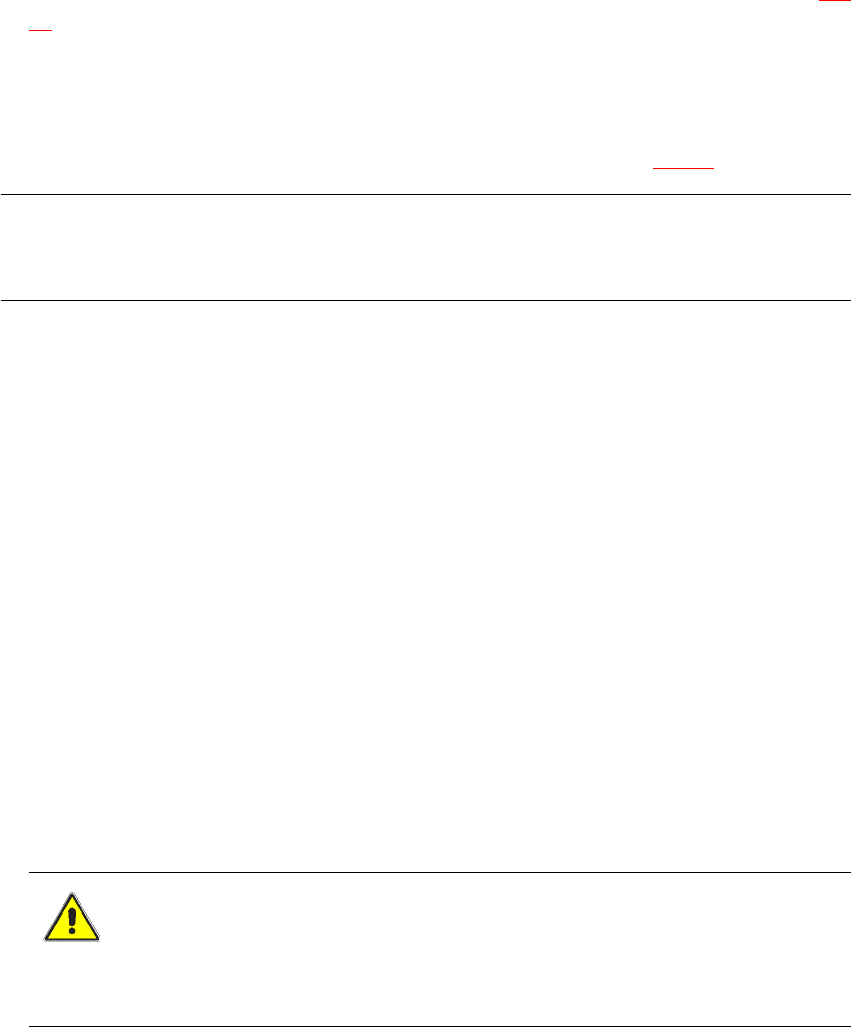
Æ Check that the pick-up position for components in the S feeders has been correctly set (see
example below).
Example for 8mm S feeders 5
5
Fig. 5.7 - 1 Pick-up position for components > 3 mm and </=
3 mm
Æ Check to see if all the plugs of the feeders are plugged in to the correct sockets.
5.7.2 ... on the 8 mm S tape feeder
Æ NEVER open the cover flap without first releasing the tension of the cover foil remover.
Æ Insert the tape material over the spring into the tape feeder.
5.7.3 ... on the tape container
Æ Insert the dividing plates correctly (see Fig. 5.3 - 2).
Æ Use spindles for large tape reels.
Component pick-
up position
> 3 mm
Component pick-
up position
≤ 3 mm
Width
User Manual SIPLACE HF Series 5 Tasks on the machine
Software Version SR.505.xx 05/2004 US Edition 5.7 Avoiding track errors
223
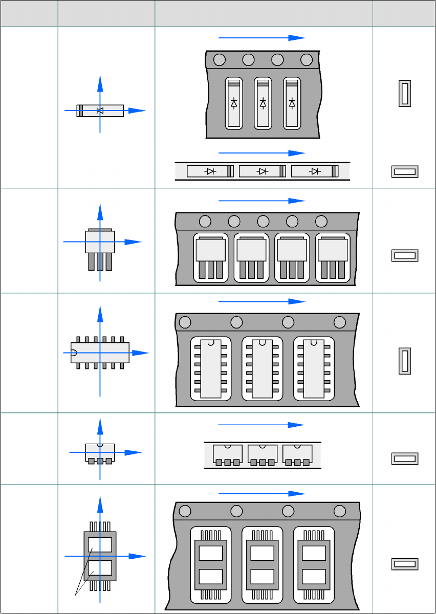
5.7.4 Component coordinate system and pick-up angle
5
Fig. 5.7 - 2 Position of the component and its pick-up angle
Special
component
Stick maga-
zine:
Chip-
components
with polarity
0402
2220
The anode must be
aligned with the +X
coordinate.
Package form
type
Coordinate system
Position in the feeder
Pick-up angle/
nozzle angle
Tape:
SOT 23
Stick maga-
zine:
Tape:
Tape:
SO-IC
DIL-IC
SOT 194
Tape:
Holes
Y
X
Y
X
Y
X
Y
X
Y
X
90°
90°
0°
90°
-90°
0°