00193922-01.pdf - 第330页
7 Station extensions User Manual SIPLACE HF Series 7.11 Coplanarity laser module Software Version S R.505.xx 05/2004 US E dition 330 7 Fig. 7.1 1 - 3 Identification for laser class 1 The inter lock line is conn ected in …
User Manual SIPLACE HF Series 7 Station extensions
Software Version SR.505.xx 05/2004 US Edition 7.11 Coplanarity laser module
329
Safety: The coplanarity laser module conforms to laser class 1, when
installed in the machine. The module will not work when off the
machine unless further devices are installed or the protective func-
tions are modified. If the protective functions on the device are
bypassed, the machine automatically conforms to laser class 3B -
(Risk of injury to eyes and skin) and thus requires protective mea-
sures to VBG 93.
7.11.3 Safety instructions
DANGER
NEVER modify or bypass safety devices on the coplanarity laser module! 7
With no protective measures, the coplanarity
laser module conforms to laser class 3B.
(7.11 - 2
).
This means there is a risk of injury to eyes
and skin! For this reason, you should
NEVER
bypass the safety devices!
Fig. 7.11 - 2 Identification for laser class 3B
The following safety devices must be installed on the machine if the laser module is to be oper-
ated in laser class 1 without risk to the eyes and skin:
Invisible laser radiation
Do not expose the beam
Class 3 B Laser Product
1mW max., 670 nm;
as per IEC 825-1(1993)
7 Station extensions User Manual SIPLACE HF Series
7.11 Coplanarity laser module Software Version SR.505.xx 05/2004 US Edition
330
7
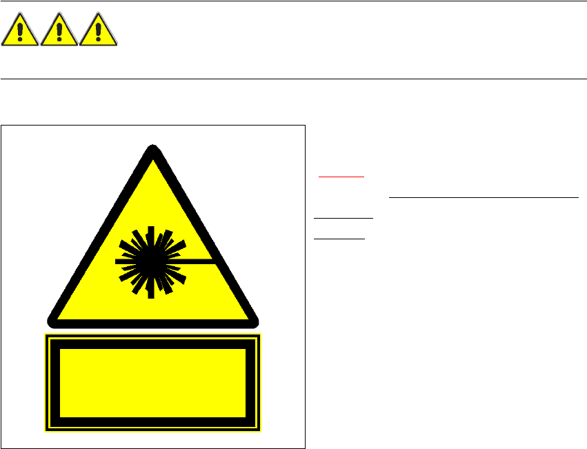
Fig. 7.11 - 3 Identification for laser class 1
The interlock line is connected in series with the switches for the protective hood. This protective
function is maintained even if the key switch is turned to bypass the protection. This means that
the laser module can only be used if the machine is closed!
DANGER
The safety guarantee is automatically invalidated if safety devices are modified or bypassed!
The user must also conform to the guidelines issued by the umbrella organization of employers'
liability insurance associations – VBG 93 – i.e.:
- Registration with the employers’ liability insurance association
- Appointment of a laser protection officer
Drawing up guidelines for use of the module 7
Class 1
Laser Product

User Manual SIPLACE HF Series 7 Station extensions
Software Version SR.505.xx 05/2004 US Edition 7.11 Coplanarity laser module
331
7.11.4 Overview
7.11.4.1 Analysis unit
The coplanarity laser module consists of two components: the analysis unit with its control sec-
tion, and the laser module. The analysis unit is located in the computer unit (see Fig. 7.11 - 4
).
The operating state is indicated by three green LEDs on the front panel of the analysis unit:
Press the RESET key to initialize the coplanarity laser module.
7.11.4.2 Laser module
The laser module is fixed to a supporting frame (see Fig. 7.11 - 5).
Two red LEDs and one green LED signal the operating states of the laser module:
LED (see Fig. 7.11 - 4)On Off
1 green 5 operating voltage No voltage
2 green 12V operating voltage No voltage
3 green Laser module in use Laser module switched off
LED (see Fig. 7.11 - 5)On Off
4 red OUT OF RANGE
(outside the measuring range)
–
5 red POOR TARGET
(component is insufficiently reflective)
–
6 green Laser module in use Laser module switched off