00193922-01.pdf - 第203页
User Manual SIPLAC E HF Series 4 Setting up and commissioning Software Version SR.505.xx 05/2004 US Edition 4. 5 Setting up the placement machine 203 4.5.15.1 Removing the ai r connectio n on the component trolley dockin…
4 Setting up and commissioning User Manual SIPLACE HF Series
4.5 Setting up the placement machine Software Version SR.505.xx 05/2004 US Edition
202
(4) M24x90 hexagon socket head screw
Æ Check the required PCB transport height.
Æ If the placement machine has been aligned, use the size 19 Allen key to tighten the hexagon
socket head screws M24x90 (Pos. 4) for holding the clamps on all the machine feet (item 3).
Æ Unscrew the "HS50" machine foot until it is seated firmly on the ground.
Æ Make sure that you do not unscrew the "HS50" machine foot so far that the machine is no
longer adjusted.
4
4
4
4
4
4
4
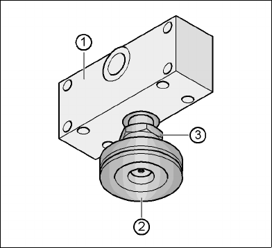
Fig. 4.5 - 23 Aligning and locking the "HS50" machine foot
(1) spacer
(2) "HS50" machine foot
(3) M24 lock nut
4
Æ Use the spirit level to ensure that the placement machine is precisely aligned.
Æ Fix the air connection to the cylinder of the docking unit if you previously removed it in order to
adjust the PCB transport height of 830 mm.
Æ Use the size 65 open-ended spanner to tighten the M24 lock nut (item 4).
User Manual SIPLACE HF Series 4 Setting up and commissioning
Software Version SR.505.xx 05/2004 US Edition 4.5 Setting up the placement machine
203
4.5.15.1 Removing the air connection on the component trolley docking unit
4
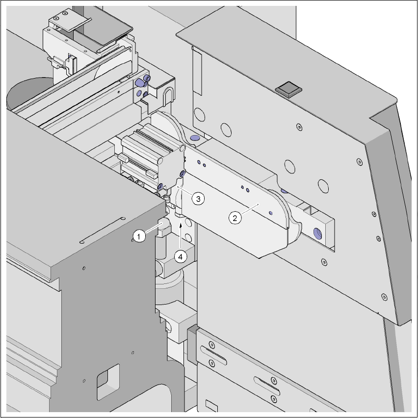
Fig. 4.5 - 24 Air connection on the cylinder of the component trolley docking unit
4
(1) M24 x 80 hexagon head screw
(2) Component trolley docking unit
(3) Cylinder
(4) Air connection, hexagon nut M10
Æ Use the size 17 open-ended spanner to remove the air connection on the docking unit.
4 Setting up and commissioning User Manual SIPLACE HF Series
4.6 Adapting the component trolley to the PCB transport height Software Version SR.505.xx 05/2004 US Edition
204
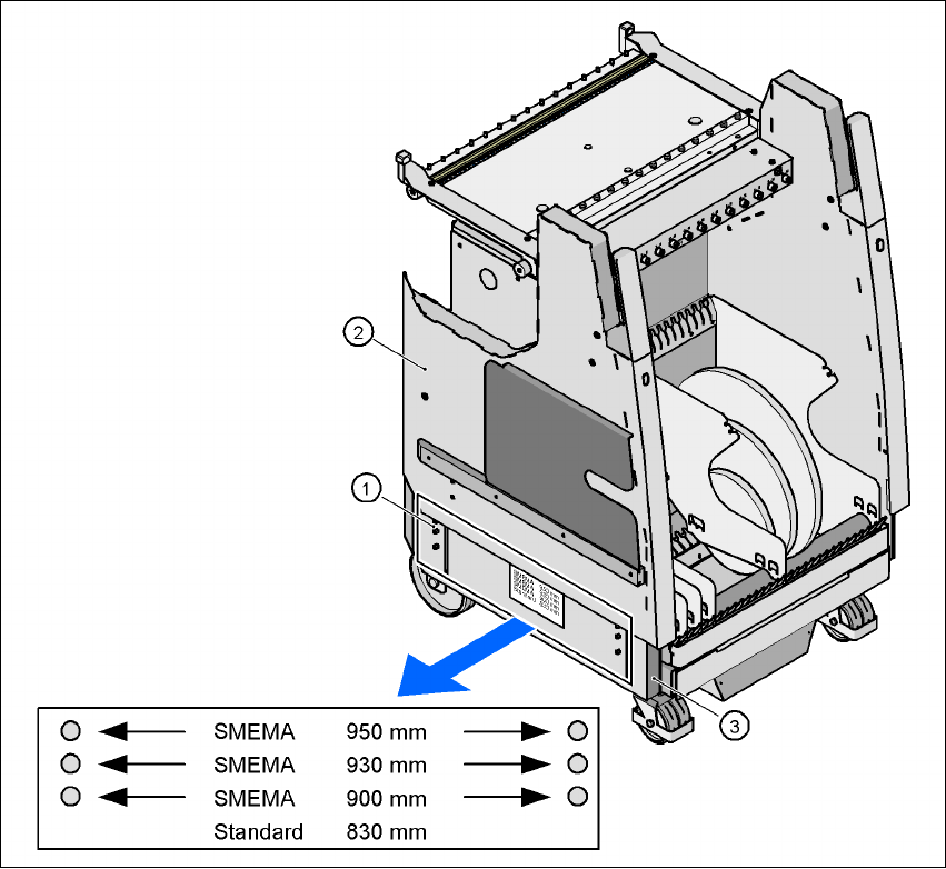
4.6 Adapting the component trolley to the PCB trans-
port height
The component trolley can be set to the following PCB transport heights with just a few simple
actions:
830 mm ± 15 mm Standard height
900 mm ± 15 mm SMEMA height
930 mm ± 15 mm SMEMA height
950 mm ± 15 mm SMEMA height 4
4
Fig. 4.6 - 1 Component trolley with a PCB transport height of 950 mm
(1) Pins for marking the height
(2) Component trolley, top part
(3) Component trolley, chassis