00193922-01.pdf - 第272页
6 Component handling User Manual SIPLACE HF Series 6.4 Matrix tray changer Software Version S R.505.xx 05/2004 US E dition 272 *) Waffl e tray carrier 6 6 6.4.2.2 Electrical ratings 6 6.4.2.3 Noise emissions 6 6.4.2.4 Pe…

User Manual SIPLACE HF Series 6 Component handling
Software Version SR.505.xx 05/2004 US Edition 6.4 Matrix tray changer
271
6.4.2 Technical data
6.4.2.1 Dimensions, weight, other data
6
Tower 1 (XL) Tower 2
Dimensions
Length x width
Height
1305 x 600 mm²
1490 mm for 830 mm PCB transport height
1560 mm for 900 mm PCB transport height
1590 mm for 930 mm PCB transport height
1640 mm for 950 mm PCB transport height
Weight (basic equipment)
Approx. 500 kg (with cassettes and waffle-pack tray carri-
ers)
Weight (fully equipped) Approx. 534 kg (with components)
Weight (moving mass) Approx. 80 kg Approx. 43.5 kg
PCB magazine size (L x W x H) 391.2 x 305.6 x 93.3 mm³ 352.7 x 154.8 x 133.8 mm³
PCB magazine weight
(fully equipped)
(without waffle tray carrier)
Approx. 11 kg
Approx. 1.7 kg
Approx. 7.5 kg
Approx. 1.35 kg
Weight of the waffle tray carrier 850 g 150 g
Dimensions of the
waffle tray carrier (L x W x H) 386.5 x 295.8 x 11.1 mm³ 371 x 146 x 10.1 mm³
Distance from PCB magazine to
magazine
96 mm 135 mm
Distance from level to level 12 mm 11.8 mm
Vertical travel 444 mm (1st to 30th FMT
*
)
511.2 mm (1st to 40th waffle
tray carrier
*
)
Horizontal travel between outgoing
and pick-up position Approx. 647 mm Approx. 638 mm
Storage capacity 30 XL waffle tray carriers
with 60 JEDEC or 30 special
magazines of maximum size
40 waffle tray carrier with 40
Jedec waffle trays
Changeover time (over 5 levels) Approx. 2 sec Approx. 1.5 sec
Max. height of component and waffle
tray, including tolerances
all levels filled
one level free
two levels free
8.5 mm
19.5 mm
31.5 mm
8.5 mm
19.5 mm
-

6 Component handling User Manual SIPLACE HF Series
6.4 Matrix tray changer Software Version SR.505.xx 05/2004 US Edition
272
*) Waffle tray carrier 6
6
6.4.2.2 Electrical ratings
6
6.4.2.3 Noise emissions
6
6.4.2.4 Permitted environmental factors
6
Max. floor loading
(fully equipped)
per foot
per roller
6.93 kg/cm²
356 kg/cm²
Tower 1 (XL) Tower 2
Supply voltage
3 x 400 VAC, 50 Hz (Europe)
3 x 208 VAC, 60 Hz (USA)
Total power 1.5 kW
Rated current
2.7 A at 3 x 400 VAC
4.2 A at 3 x 208 VAC
Fuses 3 x 16 A
Rated power consumption of the largest consumer 2 A
Maximum noise emissions 74 dB (A)
Room temperature Between 15 °C and 35 °C
Atmospheric humidity
30 - 75 %
(No higher than 45% on average to prevent any
possibility of condensation on the machine)
User Manual SIPLACE HF Series 7 Station extensions
Software Version SR.505.xx 05/2004 US Edition 7.1 Nozzle changer
273
7 Station extensions
7.1 Nozzle changer
Nozzle changers can greatly increase the flexibility of the placement heads for processing differ-
ent types of component. If the placement program requires a nozzle change, then the placement
head automatically returns the old nozzle to the nozzle holder and picks up the new nozzle. Noz-
zles that were separated out during the vacuum check can also be quickly changed.
It is significantly more exact and faster to pick up nozzles from a nozzle changer than would be
possible manually. When placing small components, it is essential to minimize the radial eccen-
tricity during nozzle rotation.
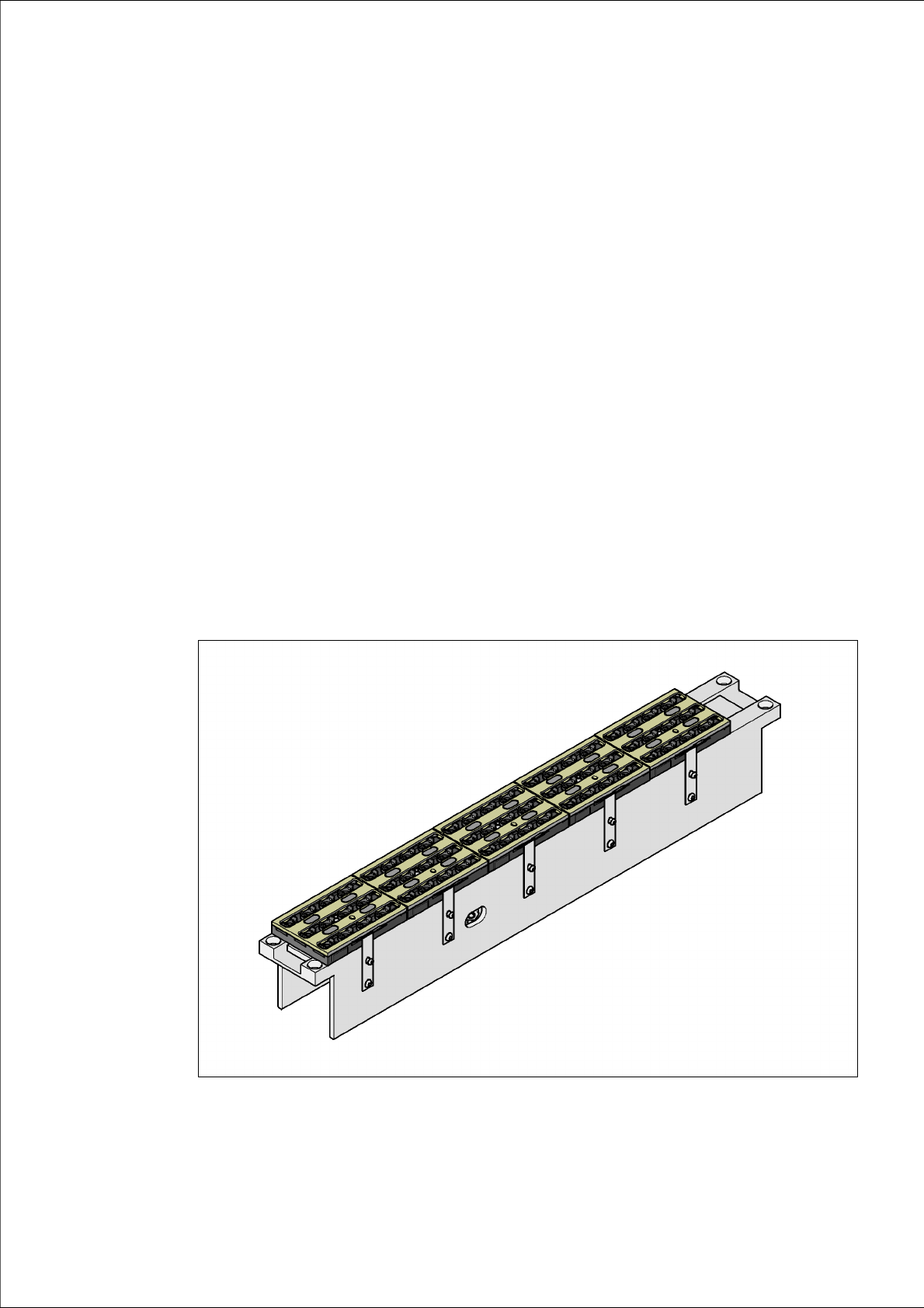
7.1.1 Nozzle changer for the 12-segment Collect&Place head
This nozzle changer can hold up to 5 magazines, each with 12 nozzle holders. The magazines
are seated on a common support. They are centered using two parallel pins and fixed in place with
clips.
7
Fig. 7.1 - 1 Nozzle changer for the 12-segment Collect&Place head