00193922-01.pdf - 第295页
User Manual SIPLAC E HF Series 7 Station extensions Software Vers ion SR.505.xx 05/2004 US Edition 7.1 Nozzle c hanger 295 7.1.3.3 Position of the nozzl e changers for the T w inHead on the HF/3 placement machine One noz…
7 Station extensions User Manual SIPLACE HF Series
7.1 Nozzle changer Software Version SR.505.xx 05/2004 US Edition
294
7.1.3.2 Position of the nozzle changers for the TwinHead on the HF placement machine
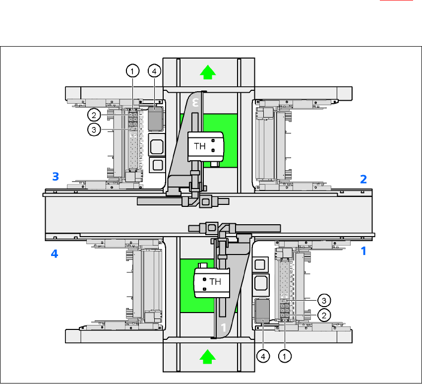
A nozzle changer for the TwinHead may be installed at locations 1 and 3 (item 1 in Fig. 7.1 - 18).
This gives a total capacity of 2 nozzle changers with 24 magazines and a total of 48 nozzle hold-
ers.
7
Fig. 7.1 - 18 Position of the nozzle changers for the TwinHead on the HF placement machine
(1) Nozzle changer
(2) Standard magazine
(3) Magazine for special nozzles or grippers
(4) Component reject bin
7
7
User Manual SIPLACE HF Series 7 Station extensions
Software Version SR.505.xx 05/2004 US Edition 7.1 Nozzle changer
295
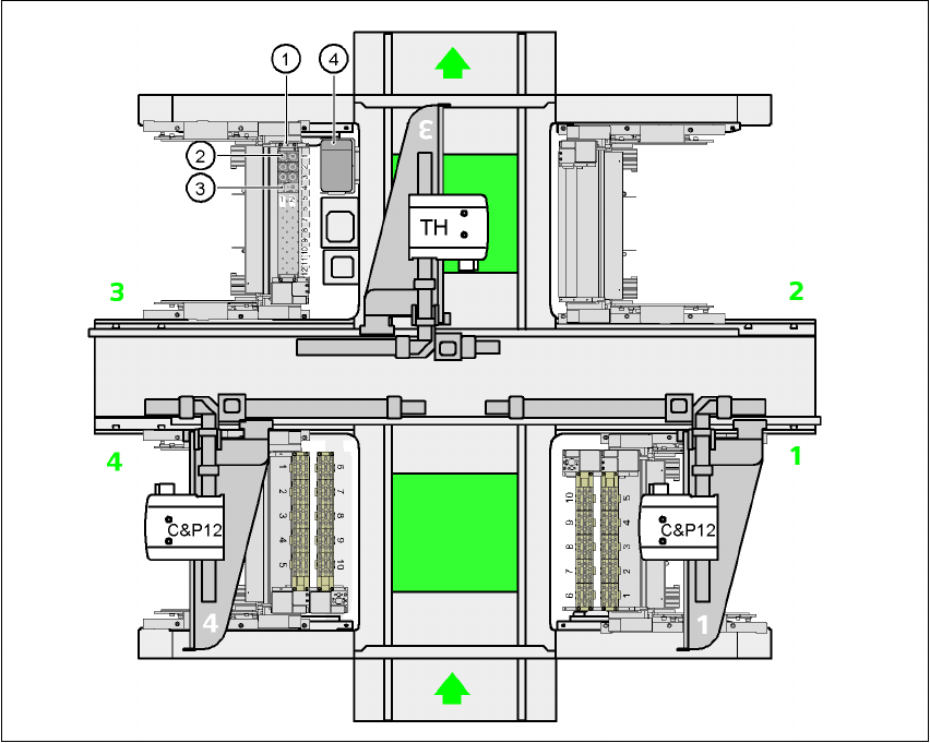
7.1.3.3 Position of the nozzle changers for the TwinHead on the HF/3 placement machine
One nozzle changer may be installed at location 3 for the TwinHead. This gives a total capacity of
12 magazines with a total of 24 nozzle holders.
7
Fig. 7.1 - 19 Position of the nozzle changers for the TwinHead on the HF/3 placement machine
(1)Nozzle changer
(2)Standard magazine
(3)Magazine for special nozzles or grippers
(4)Component reject bin
7 Station extensions User Manual SIPLACE HF Series
7.1 Nozzle changer Software Version SR.505.xx 05/2004 US Edition
296
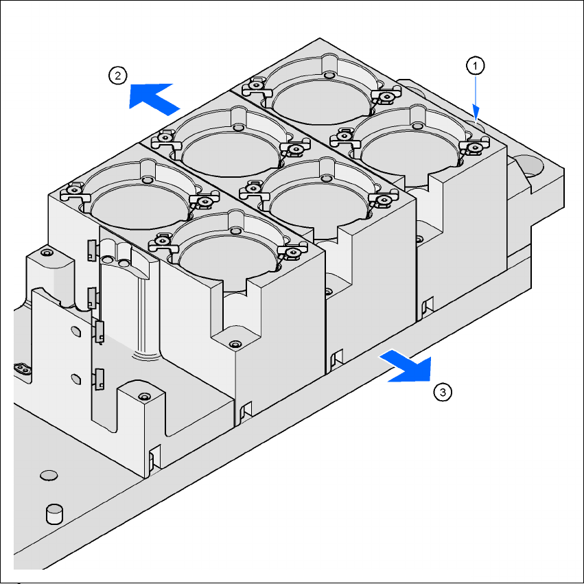
7.1.3.4 Assembly
The nozzle changer is fixed to the component trolley docking unit.
7
Fig. 7.1 - 20 Assembly position
(1) Marking hole
(2) Operator side
(3) Arrow pointing toward the PCB conveyor
7
Æ Align the nozzle changer so that the marking hole (item 1) is on the left, as viewed by the op-
erator.