00193922-01.pdf - 第255页
User Manual SIPLAC E HF Series 6 Component han dling Software Version SR.505.xx 05/2004 US Edition 6.2 Technical data for the feeders 255 6.2.17.2 T echnical dat a Item no. 001 17010-xx 6 Assign ed locations 3 6 Componen…
6 Component handling User Manual SIPLACE HF Series
6.2 Technical data for the feeders Software Version SR.505.xx 05/2004 US Edition
254
6.2.16.3 Data entry
Define the waffle-pack trays as described in the SIPLACE Pro operating instructions. 6
6.2.17 Dip module
6
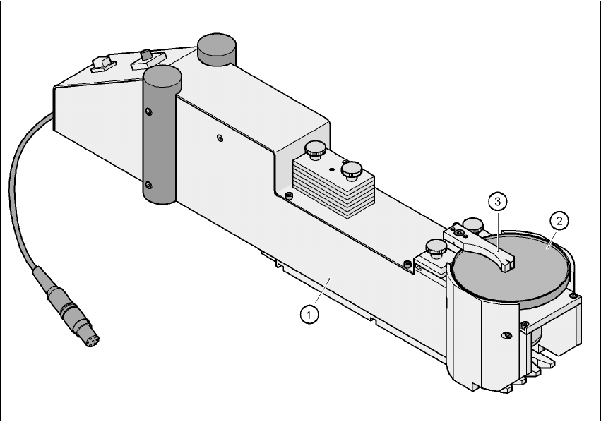
Fig. 6.2 - 17 Dip module
(1) Dip module
(2) Rotating plate
(3) Squeegee
6.2.17.1 Principle of dip fluxing
The dip module (item 1) is used to wet flip-chip and CSP components with flux or conductive ad-
hesive.The flux holder is a rotating plate (item 2) on which a thin film of flux (e.g. 40 µm) is created
with a squeegee (item 3). This method is particularly suitable for highly viscous (honey-like) fluxes.
The amount of flux required for the process is reduced to a minimum coating thickness since only
the undersides of the bumps have to be wetted.
The dip module is suitable for all placement heads. It is regarded as a standalone type of conveyor
by the set-up optimization. There is no limit to the number of dip modules at the individual loca-
tions.
User Manual SIPLACE HF Series 6 Component handling
Software Version SR.505.xx 05/2004 US Edition 6.2 Technical data for the feeders
255
6.2.17.2 Technical data
Item no. 00117010-xx 6
Assigned locations 3 6
Component size max. 36 x 36 mm²
depending on the placement head type 6
Possible coating thicknesses 25, 35, 45, 55, 65, 75 µm 6
Time required to change the coating thickness Less than 1 min. 6
Gap height tolerance ± 5 mm 6
Plate rotating speed Programmable from 0 - 10 sec.
in 0.1 sec. increments 6
Component dip time Programmable from 0 - 2 sec.
in 0.1 sec. increments 6
Flux Highly viscous flux, conductive adhesive 6
6
6 Component handling User Manual SIPLACE HF Series
6.3 Component trolley Software Version SR.505.xx 05/2004 US Edition
256
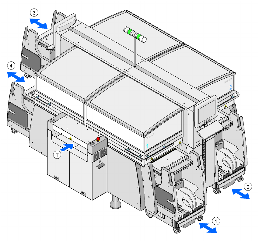
6.3 Component trolley
Up to four component trolleys may be docked to the SIPLACE HF placement machine. The loca-
tions are numbered as shown in the diagram below.
Fig. 6.3 - 1 Locations for the component trolleys
1, 2, 3, 4 Location no. 1, 2, 3, 4
T Direction of PCB transport
The component trolleys are stand-alone modules that can be set up at an external set-up area
with feeders. This means that the production process only has to be interrupted briefly in order to
change the component trolley.