KE-3020_SPE_EN.pdf - 第11页
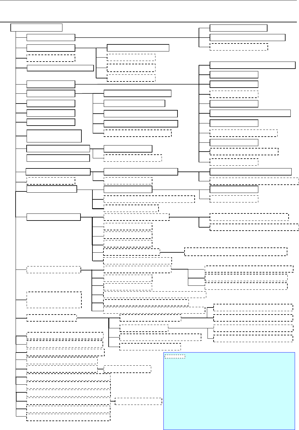
- 7 - 3.2. KE- 3020R Sy st em Configuration Power unit Cabinet Eme r gency st op button A TX power supply (with UPS function) Leakage breaker *1 CPU Liquid crystal display (T ouc h p anel) Mouse HOD SSD Comm unicati on p…
- 6 -
3.
System Configuration
3.1. KE-3020 System Configuration
Power unit
Cabinet
Emergency stop button
ATX power supply (with UPS function)
Leakage breaker *1
CPU
Liquid crystal display (Touch panel)
Mouse
HOD
SSD
Communication port (Ethernet board)
Touch panel
Rear side operation unit *1
DVD/CD-ROM drive (USB)
FD drive (USB)
Keyboard
USB port
Signal tower with the buzzer
Mini signal light *1
I/O control CPU
Motor control unit
X-Y control unit
Placing head
Laser recognition head (LNC60)
IC head (CDS)
Offset Correction Camera (OCC) L,R
Height Measurement System (HMS)
Bad Mark Reader (BMR) *1
Vacuum pump
Main line filter *1
Automatic PWB transportation Width adjustment device
Pin reference *1
L-Wide *1, *3
Feeder float detecting function
SOT direction check function *1
Components Verification System (CVS)
*1
Feeder position indicator function (FPI) *1
Flexible Calibration System (FCS)
External Programming Unit (EPU)
Intelligent Shopfloor Solutions (IS)
Intelli Stocker *2
Connector bracket *1
Trash box
Intelli feeder trolley for mechanical feeder *2
Tape feeder, Bulk feeder, Stick feeder *2
IC collection belt
Tape cutter unit *1
Component supply unit Tape feeder, Stick feeder *2
Tray feed device
MTC
(
TR-6DNX/6DXLX, 6SNX/6SXLX
)
MTS (TR-5DNX/SNX)
DTS (Dual Tray Server)
Tray holder
Super Foot *1
Caster *1
*3
MNVC *1
High-resolution camera (vision field: 27 mm) *1
IC collection belt
Feeder trolley for electric feeder(EF)/(RF)*7
Intelli feeder trolley for electric feeder *2
TR-1SNR for mechanical feeder bank
TR-1EB for electric feeder bank
Tray holder for mechanical feeder bank
Tray holder for electric feeder bank
Coplanarity function
*1
Load calibration stage *1
Offset Placement After Solder Screen-printing *1
KE-3020
Ionizer
*1
Component DB function*4
Mechanical feeder bank
Automatic Tool Changer
(ATC)
Air pressure unit piping system
Load control nozzle
Placement station
PWB conveyor unit
Outline reference
VCS camera
Standard camera (vision field: 54
mm)
Feeder trolley for mechanical feeder
Batch feeder change function *1
Batch feeder change function *1
Electric feeder bank *1
Vision Centering System(VCS)
Component supply unit
Fluxer *1
Feeder bank for both a
mechanical feeder and an
electric feeder *1 *5
Tape reel attaching platform
ETF Tape reel attaching platform(EF)/(RF)
RF-ETF attachment *6
Production support system (IS Lite,JaNets)
Production management system (IFS-NX)
Equipment or a function surrounded by a dashed line is optional.
*1 An option indicated with an asterisk "*" is to be mounted on the main unit at
the factory.
*2 To use the production management system, Applicable to FRID is required.
(factory-set option).
*3 It is available for only machines handling L-PWB.
*4 Another PC is necessary to use Component DB function.
*5 See the description of each feeder bank for an option to be shared (only the
function for a feeder exchange trolley is supported).
*6 Attach this component when electric feeders are used by a feeder trolley
(RF).(If you use the EF series electric feeder attachment, non-teaching and
synchronous adsorption guarantee are excluded.)
*7 It's necessary to change the cutter unit to the latest to use "Feeder exchange
trolley RF".
Offline power supply for an electric bank (PW01/02)
- 7 -
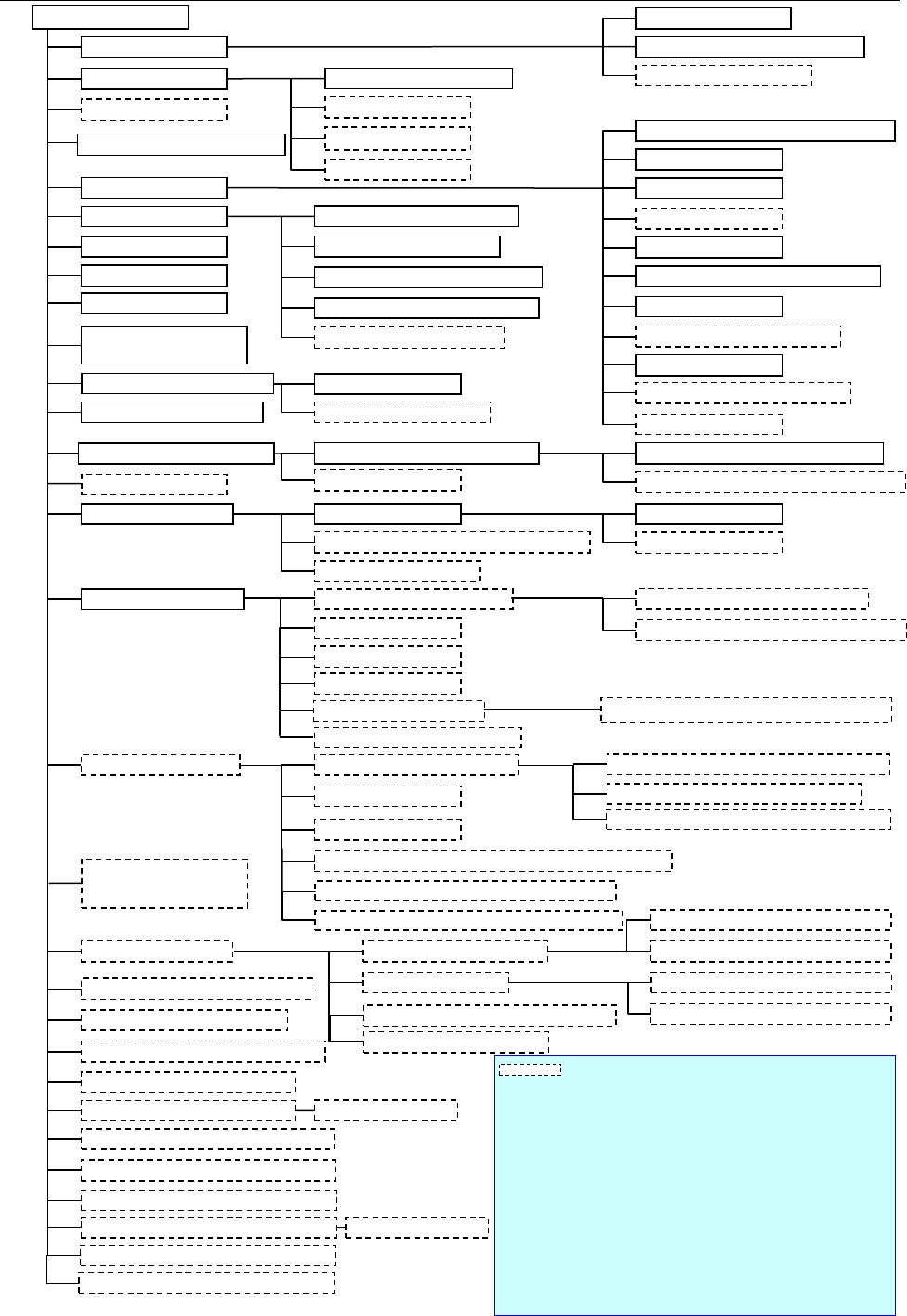
3.2. KE-3020R System Configuration
Power unit
Cabinet
Emergency stop
button
ATX power supply (with UPS function)
Leakage breaker *1
CPU
Liquid crystal display (Touch panel)
Mouse
HOD
SSD
Communication port (Ethernet board)
Touch panel
Rear side operation unit *1
DVD/CD-ROM drive (USB)
FD drive (USB)
Keyboard
USB port
Signal tower with the buzzer
Mini signal light *1
I/O control CPU
Motor control unit
X-Y control unit
Placing head
Laser recognition head (LNC60)
IC head (FMLA)
Offset Correction Camera (OCC) L,R
Height Measurement System (HMS)
Bad Mark Reader (BMR) *1
Vacuum pump
Main line filter *1
Air pressure unit piping system
PWB conveyor unit
Placement station
Automatic PWB transportation Width adjustment device
Outline reference
Pin reference *1
L-Wide *1, *3
Feeder float detecting function
SOT direction check function *1
Components Verification System (CVS)
*1
Feeder position indicator function (FPI) *1
Flexible Calibration System (FCS)
External Programming Unit (EPU)
Intelligent Shopfloor Solutions (IS)
Intelli Stocker *2
Batch feeder change function *1
Connector bracket *1
Trash box
Feeder trolley for mechanical feeder
Intelli feeder trolley for mechanical feeder *2
Component supply unit
IC collection belt
Batch feeder change
function *1
Tape cutter unit *1
Component supply unit Tape feeder, Stick feeder *2
Tray feed device
MTC
(
TR-6DNX/6DXLX, 6SNX/6SXLX
)
MTS (TR-5DNX/SNX)
DTS (Dual Tray Server)
Tray holder
Super Foot *1
Caster
*1*3
VCS camera
MNVC *1
Vision Centering System(VCS)
Standard camera (vision field: 54
mm)
High-resolution camera (vision field: 27 mm) *1
IC collection belt
Feeder trolley for electric feeder (EF)/(RF)*7
Intelli feeder trolley for electric feeder *2
TR-1SNR for mechanical feeder bank
TR-1EB for electric feeder bank
Tray holder for mechanical feeder bank
Tray holder for electric feeder bank
Coplanarity function
*1
Load calibration stage *1
Load control nozzle
Offset Placement After Solder Screen-printing *1
KE-3020R
Ionizer
*1
Component DB function *4
Automatic Tool Changer
(ATC)
Mechanical feeder bank
Electric feeder bank *1
Tape feeder, Bulk feeder, Stick feeder *2
Fluxer *1
Feeder bank for both a
mechanical feeder and an
electric feeder *1 *5
Tape reel attaching platform
ETF Tape reel attaching platform (EF)/(RF)
Equipment or a function surrounded by a dashed line is
optional.
*1 An option indicated with an asterisk "*" is to be mounted on the
main
unit at the factory.
*2 To use the production management system, Applicable to FRID is
required. (factory-set option).
*3 It is available for only machines handling L-PWB.
*4 Another PC is necessary to use Component DB function.
*5 See the description of each feeder bank for an option to be shared
(only the function for a feeder exchange trolley is supported).
*6 Attach this component when electric feeders are used by a feeder
trolley (RF).(If you use the EF series electric feeder attachment,
non-teaching and synchronous adsorption guarantee are excluded.)
*7
It's necessary to change the cutter unit to the latest to use "Feeder
exchange trolley RF".
Production support system (IS Lite,JaNets)
Production management system (IFS-NX)
RF-ETF attachment *6
Offline power supply for an electric bank (PW01/02)
- 8 -
4.
Specifications
4.1. Features of each model
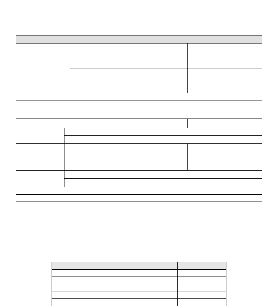
① Basic specifications
KE-3020 and KE-3020R
Board specifications
L-PWB
XL-PWB
Board dimensions
Standard 410 x 360 mm 610 x 560 mm
L-Wide PWB
(Option)
510 x 360 mm -
Board transport reference position Front side or rear side Front side
Supported languages
English, Japanese, Chinese
Conveyor height
900±20mm (for Japan, China, and Southeast Asian countries)
950±20mm (for Europe and the U.S.A.)
Component height 12 mm (NC), 20 mm (HC) 25 mm (EC)
Component size
* See Note 1.
Laser recognition
0402 to □33.5 mm or Length of a diagonal line:47 mm
Image recognition
1.0 ×0.5 mm to □74 mm or 50 ×150 mm
Component
placement speed
* See Note 2 and 4
Chip component
(IPC9850)
17,100(CPH) 15,300(CPH)
IC component
* See Note 3.
5,800(CPH) 4,600(CPH)
Placement accuracy
* See Note 1.
Laser recognition
±
50
μ
m (Cpk
≧
1)
Image recognition
±30μm (±40μm for MNVC)
Number of component to be placed A maximum of 160 types(on a Electric Double Tape feeder)
EN Specifications
Enable
* Note 1: See Section 4.4 “Applicable Component” and Section 4.5 “Component Placement
Accuracy at X, Y and θ” for details of the specifications.
* Note 2: The value changes depending on the board transport reference position/height or a component
height.
* Note 3: It is the approximate value when MNVC (option) is used and/or the components are simultaneously
picked up with 6 nozzles.
*Note 4: Except case of using the RF-ETF attachment.
② The relationship among the model names, recognition devices and heads is shown below.
KE-3020
KE-3020R
LNC60
Standard
Standard
IC head (CDS)
Standard
-
IC head (FMLA)
-
Standard
VCS
Standard
Standard
MNVC
Option
Option
• LNC60 : Enables the high-speed placement of small chip components or thin
chip-shaped components with 6 nozzles on a board.
• IC head (CDS) : Enables the placement of ICs such as large QFPs, CSPs, and BGAs on a
board.
• IC head (FMLA) : Enables recognition with laser or recognition with a VCS.
An IC head (FMLA) can use all types of nozzles such as a gripper nozzle
and a customized nozzle.
• VCS : Enables the placement of IC components using image recognition on a
board. Moreover, high-resolution camera (Option) can be added to it.
• MNVC : Enables the placement using image recognition with LNC60.
Components such as small QFPs, CSPs, and BGAs can be then placed at high
speed on a board.