KE-3020_SPE_EN.pdf - 第23页
- 19 - 4.7.6. Function cor recting th e P W B positi ons Field of vision for recognizing the PWB reference marks □ 6. 3 mm (ca mera ’ s field of vision for recognition). Figur e 6 Field of vision for recog nizing t he PW…
- 18 -
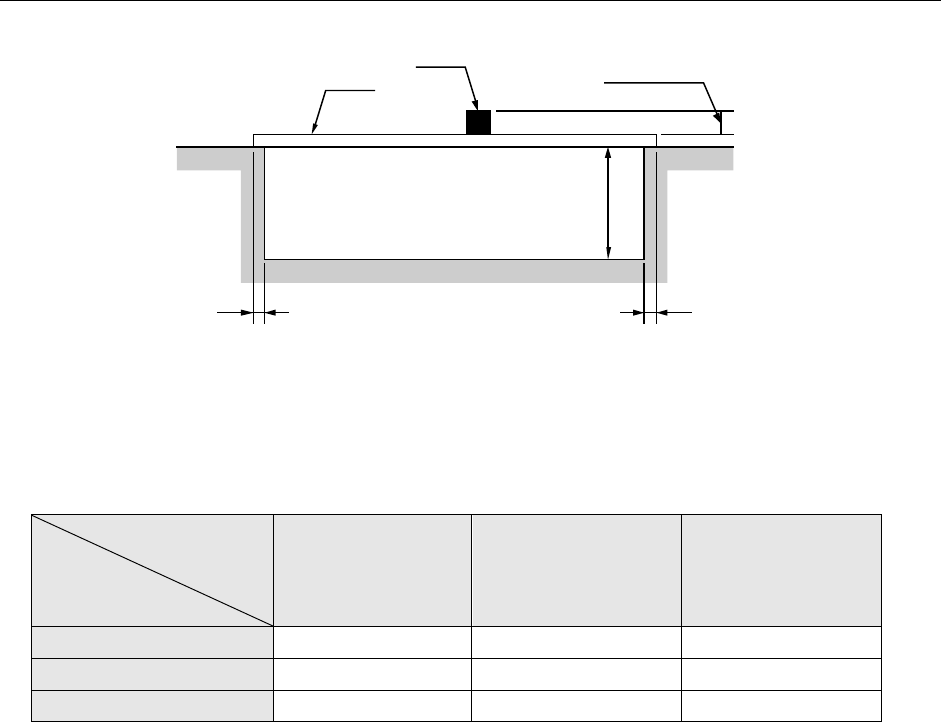
4.7.5. Area where components can be placed on the board (top and bottom)
Figure 5 Area where components can be placed on
the top and the bottom sides of a board
Maximum heights of components that can be placed (Unit: mm)
Component size
Specification
of component height
Component diagonal
less than 50 mm
Component diagonal
50 mm or more to
less than 88 mm
Component diagonal
88 mm or more
NC specification 12mm 12mm 5mm
HC specification 20mm 20mm 5mm
EC specification 25mm 20mm 5mm
PWB transportation specifications (factory-set)
L- and L-Wide PWB specifications:Front specification or rear specification
XL-PWB specifications:Front specification
PWBs clamping method
This is a method to use the PWB top surface as a reference to have both the PWB front and
rear ends each at the fixed and movable sides supported to the transport rails, then, to clamp
the PWBs.
PWB width adjusting methods
* Standard: Manually adjusting method with your hand
* Option: Automatic PWB width adjusting method via a motor
(Minimum board size: 50.0 mm x 50.0 mm)
PWB positioning reference
* Shape reference
* Pine reference (optional)
Board
Component
MAX. 40 mm
3 mm
3 mm
H: See the table
below for the dimension.
- 19 -
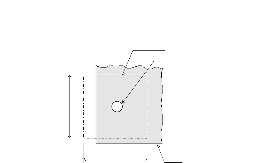
4.7.6. Function correcting the PWB positions
Field of vision for recognizing the PWB reference marks
□6. 3 mm (camera’s field of vision for recognition).
Figure 6 Field of vision for recognizing the PWB reference marks
Window size for recognizing the PWB reference marks
This size can be changed within a maximum of 6.3 mm, subject to securing a clearance
between the recognition mark and its surrounding area.
Kinds of recognition marks and corrective method
- PWB reference mark
Two or three marks are located on a PWB to correct the entire PWB.
When a machine detects two PWB reference marks, it corrects the positioning, angle and
expansion/contraction of the entire PWB. When detecting three PWB reference marks,
it corrects the perpendicularity in the X and Y direction also.
- Component positioning marks
If a component such as an IC (QFP) needs to be placed on a board very precisely, two or
three marks set on a component itself are used to correct each component placement
position.
- Marks used to position the component area
Two marks (their positions can be set as you like) are to be provided to a group of
components placement positions, and they are used to correct each component
placement position in the group.
Note
:
The position is arbitrary, subject to not aligning three (3) reference makes,
if this is the case, on one (1) straight line. (It is recommended that the reference marks should
be made at the four (4) corners of the PWBs.
Field of vision for PWBs recognition
Recognition mark
PWB
6.3mm
6.3mm
- 20 -
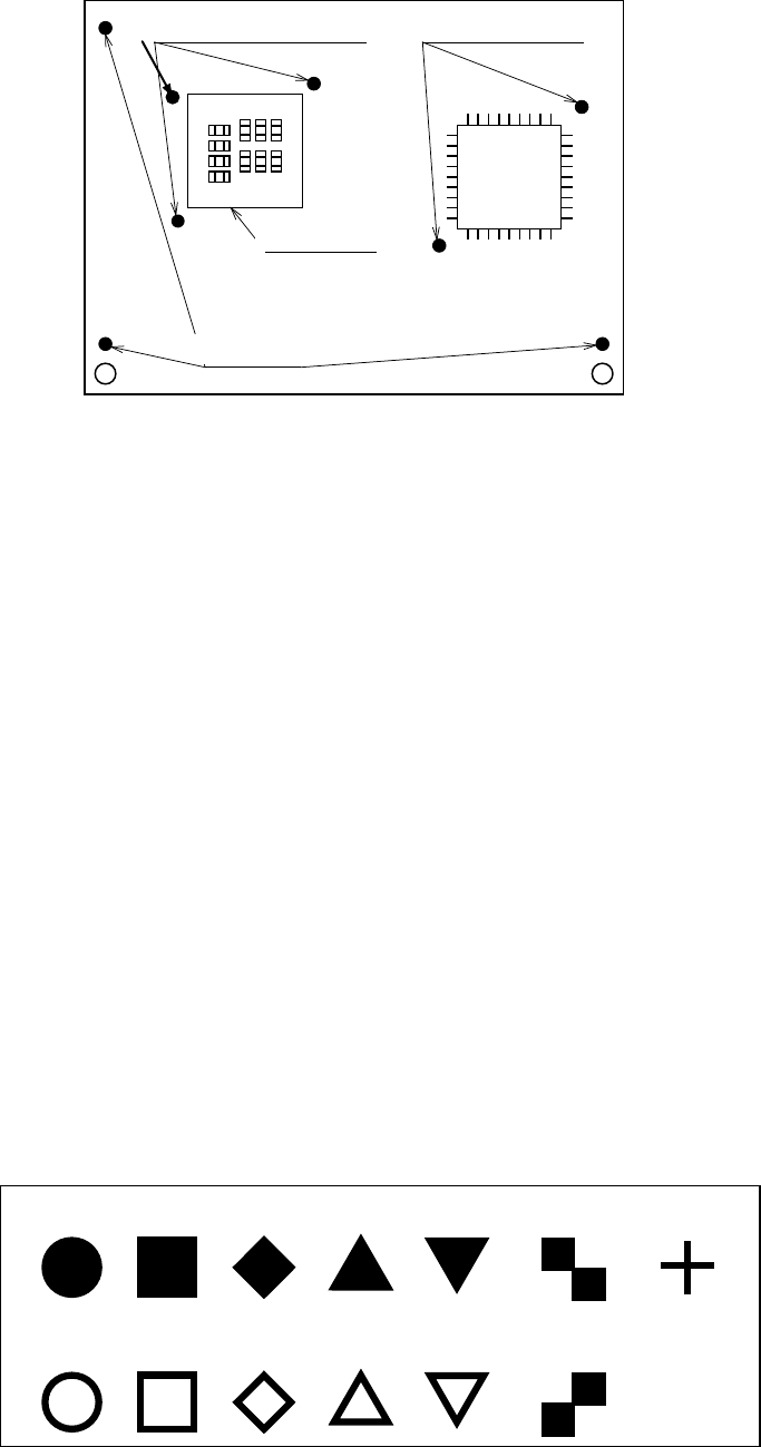
搭 載 グ ル ー プ
エ リ ア 部 品 位 置 決 め マ ー ク
部 品 位 置 決 め マ ー ク
基 準 マ ー ク
Figure 7 Reference marks and components positioning marks
Basic quality of recognition marks
- Copper not coated or coated
- It needs to have a clear contrast between the recognition mark surface and the print
wiring quality.
- It needs to have neither oxidation nor quality deterioration of the recognition marks.
Coating the recognition marks
The recognition mark surfaces shall all be coated as follows:
- Transparent antioxidant coating - Solder plating
- Nickel plating - Gold plating
- Tin plating - Hot air repeller solder coating
Marking forms
- The standard marks represent the thirteen (13) forms as shown in the following block,
“Forms of Recognition Marks.”
- For any mark other than those shown in the said block, customers shall make templates
to allow for recognition through a pattern matching.
Note 1: Up to three PWB reference marks and up to six component placement area
positioning marks are supported.
Note 2: Within a field of vision, there should be no similar form pattern other than the
subjected form patterns.
- For regular triangles, checker patterns and users’ templates, the 90°up-side-down
marks can also be recognized.
Circle
Square
Diamond
Regular
triangle
Up-side-down
triangle
Checker
pattern
Cross
Inside-blank
circle
Inside-blank
square
Inside-blank
diamond
Inside-blank
up-side-down
triangle
Checker
pattern
Inside-blank
Regular
triangle
Figure 8 Forms of Recognition Marks
The recognition marks shall all comply with EIAJ ET-7302 “Recognition marks for on-surface
placed PWBs.”
Component placement
area positioning marks
Component positioning
marks
Placement group
PWB reference marks