KE-3020_SPE_EN.pdf - 第12页
- 8 - 4. S peci ficat ions 4.1. Features of each model ① Basic speci f ications KE - 3020 and KE - 3020R Board specific ations L- PWB XL - PW B Board dimensions S tandard 410 x 360 mm 610 x 560 mm L- Wide PWB (Option) 51…
- 7 -
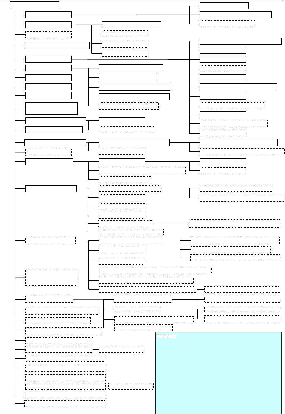
3.2. KE-3020R System Configuration
Power unit
Cabinet
Emergency stop
button
ATX power supply (with UPS function)
Leakage breaker *1
CPU
Liquid crystal display (Touch panel)
Mouse
HOD
SSD
Communication port (Ethernet board)
Touch panel
Rear side operation unit *1
DVD/CD-ROM drive (USB)
FD drive (USB)
Keyboard
USB port
Signal tower with the buzzer
Mini signal light *1
I/O control CPU
Motor control unit
X-Y control unit
Placing head
Laser recognition head (LNC60)
IC head (FMLA)
Offset Correction Camera (OCC) L,R
Height Measurement System (HMS)
Bad Mark Reader (BMR) *1
Vacuum pump
Main line filter *1
Air pressure unit piping system
PWB conveyor unit
Placement station
Automatic PWB transportation Width adjustment device
Outline reference
Pin reference *1
L-Wide *1, *3
Feeder float detecting function
SOT direction check function *1
Components Verification System (CVS)
*1
Feeder position indicator function (FPI) *1
Flexible Calibration System (FCS)
External Programming Unit (EPU)
Intelligent Shopfloor Solutions (IS)
Intelli Stocker *2
Batch feeder change function *1
Connector bracket *1
Trash box
Feeder trolley for mechanical feeder
Intelli feeder trolley for mechanical feeder *2
Component supply unit
IC collection belt
Batch feeder change
function *1
Tape cutter unit *1
Component supply unit Tape feeder, Stick feeder *2
Tray feed device
MTC
(
TR-6DNX/6DXLX, 6SNX/6SXLX
)
MTS (TR-5DNX/SNX)
DTS (Dual Tray Server)
Tray holder
Super Foot *1
Caster
*1*3
VCS camera
MNVC *1
Vision Centering System(VCS)
Standard camera (vision field: 54
mm)
High-resolution camera (vision field: 27 mm) *1
IC collection belt
Feeder trolley for electric feeder (EF)/(RF)*7
Intelli feeder trolley for electric feeder *2
TR-1SNR for mechanical feeder bank
TR-1EB for electric feeder bank
Tray holder for mechanical feeder bank
Tray holder for electric feeder bank
Coplanarity function
*1
Load calibration stage *1
Load control nozzle
Offset Placement After Solder Screen-printing *1
KE-3020R
Ionizer
*1
Component DB function *4
Automatic Tool Changer
(ATC)
Mechanical feeder bank
Electric feeder bank *1
Tape feeder, Bulk feeder, Stick feeder *2
Fluxer *1
Feeder bank for both a
mechanical feeder and an
electric feeder *1 *5
Tape reel attaching platform
ETF Tape reel attaching platform (EF)/(RF)
Equipment or a function surrounded by a dashed line is
optional.
*1 An option indicated with an asterisk "*" is to be mounted on the
main
unit at the factory.
*2 To use the production management system, Applicable to FRID is
required. (factory-set option).
*3 It is available for only machines handling L-PWB.
*4 Another PC is necessary to use Component DB function.
*5 See the description of each feeder bank for an option to be shared
(only the function for a feeder exchange trolley is supported).
*6 Attach this component when electric feeders are used by a feeder
trolley (RF).(If you use the EF series electric feeder attachment,
non-teaching and synchronous adsorption guarantee are excluded.)
*7
It's necessary to change the cutter unit to the latest to use "Feeder
exchange trolley RF".
Production support system (IS Lite,JaNets)
Production management system (IFS-NX)
RF-ETF attachment *6
Offline power supply for an electric bank (PW01/02)
- 8 -
4.
Specifications
4.1. Features of each model
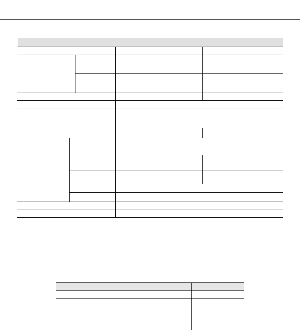
① Basic specifications
KE-3020 and KE-3020R
Board specifications
L-PWB
XL-PWB
Board dimensions
Standard 410 x 360 mm 610 x 560 mm
L-Wide PWB
(Option)
510 x 360 mm -
Board transport reference position Front side or rear side Front side
Supported languages
English, Japanese, Chinese
Conveyor height
900±20mm (for Japan, China, and Southeast Asian countries)
950±20mm (for Europe and the U.S.A.)
Component height 12 mm (NC), 20 mm (HC) 25 mm (EC)
Component size
* See Note 1.
Laser recognition
0402 to □33.5 mm or Length of a diagonal line:47 mm
Image recognition
1.0 ×0.5 mm to □74 mm or 50 ×150 mm
Component
placement speed
* See Note 2 and 4
Chip component
(IPC9850)
17,100(CPH) 15,300(CPH)
IC component
* See Note 3.
5,800(CPH) 4,600(CPH)
Placement accuracy
* See Note 1.
Laser recognition
±
50
μ
m (Cpk
≧
1)
Image recognition
±30μm (±40μm for MNVC)
Number of component to be placed A maximum of 160 types(on a Electric Double Tape feeder)
EN Specifications
Enable
* Note 1: See Section 4.4 “Applicable Component” and Section 4.5 “Component Placement
Accuracy at X, Y and θ” for details of the specifications.
* Note 2: The value changes depending on the board transport reference position/height or a component
height.
* Note 3: It is the approximate value when MNVC (option) is used and/or the components are simultaneously
picked up with 6 nozzles.
*Note 4: Except case of using the RF-ETF attachment.
② The relationship among the model names, recognition devices and heads is shown below.
KE-3020
KE-3020R
LNC60
Standard
Standard
IC head (CDS)
Standard
-
IC head (FMLA)
-
Standard
VCS
Standard
Standard
MNVC
Option
Option
• LNC60 : Enables the high-speed placement of small chip components or thin
chip-shaped components with 6 nozzles on a board.
• IC head (CDS) : Enables the placement of ICs such as large QFPs, CSPs, and BGAs on a
board.
• IC head (FMLA) : Enables recognition with laser or recognition with a VCS.
An IC head (FMLA) can use all types of nozzles such as a gripper nozzle
and a customized nozzle.
• VCS : Enables the placement of IC components using image recognition on a
board. Moreover, high-resolution camera (Option) can be added to it.
• MNVC : Enables the placement using image recognition with LNC60.
Components such as small QFPs, CSPs, and BGAs can be then placed at high
speed on a board.
- 9 -
4.2. Mechanical/Electrical Specifications
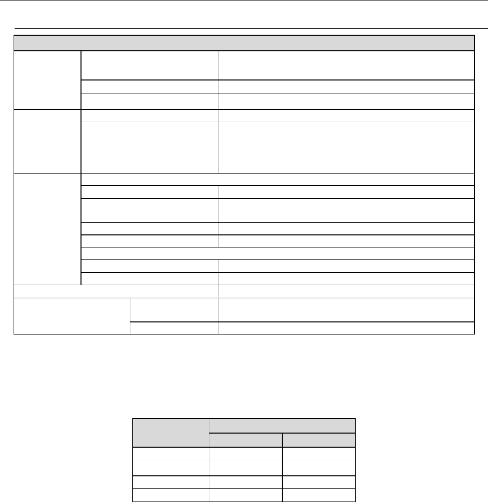
4.2.1. Usage environment conditions
KE-3020 / KE-3020R
Power
supply
Voltage
Three-phase 200V, 220V, 240V, 380V, 400V, 415V AC
±10% (See Note 1)
Frequency
50/60 Hz
Rated apparent power
2.2 kVA
Air supply
Air pressure
0.5 ± 0.05 MPa dry air
Maximum air consumption
50L/min (ANR) (See Note 2)
Environment
requirements
During operation
Ambient temperature
+ 10 to + 35 °C
Placement accuracy
guarantee temperature
+ 20 to + 25 °C
Relative humidity
30 % to 80% RH (with no condensation)
Altitude
1,000m or less
During transportation or storage
Ambient temperature
- 15°C to + 70°C
Relative humidity
20 % to 95% RH (with no condensation)
Noise
75 dB (A) or less (See Note 3)
Installation conditions
(for a EN machine)
Overvoltage
category
Category III according to IEC60664-1
Pollution degree
Degree 3 according to IEC60664-1
Note 1: No power supply cable at the primary side is attached thereto.
We make NO WARRANTIES against any accident of the primary side wiring caused by
short–circuit of the power cable and so on. Please use a 5.5-mm
2
or more diameter of
power cable for each phase. (Note: the appropriate cross-section area of the cable varies
depending on the supplied power voltage and the length of the power cable.)
Cable length
(m)
Conductor cross section (mm
2
)
200Vseries 400Vseries
Less than 20 5.5 5.5
30 8.0 5.5
40
10.0
6.0
50
14.0
6.0
・
Peak current (at AC200V 3phase power) : 40A
Note 2: ANR conditions are as follows:
Temperature = 20
°
C,
Absolute pressure = 0.1MPa (=100kPa=1bar),
Relative humidity = 65%
Note 3: This value was measured with conforming to the JIS Z8731 regulation.