KE-3020_SPE_EN.pdf - 第26页
- 22 - 5. S t anda rd Funct ions A nd Op tional Func tions 5.1. Standard 5.1.1. Component dat abase functio n The component databas e is software intended for the creation and management of “ Component data ” , w hich is…
- 21 -
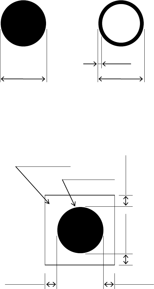
Dimensions and tolerances
The outside dimensions shall range from 0.5 mm up to 3.0mm, whose tolerance, less than
10%.
For all the inside-blank forms, the edging line width shall be more than 0.2 mm.
Figure 9
Dimensions and tolerances of recognition marks.
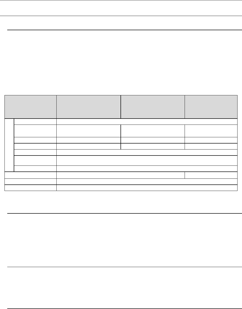
It is desirable that there is, around each recognition mark, a space having nothing of such
other marks as conductor pattern, solder resist, marking and the like, and that this space
dimensions is a larger square than the mark by 0.5 mm or more from the outer
circumference of the recognition marks.
Figure 10
Clearances of recognition marks
0.5
to 3.0mm
0.5 to 3.0mm
0.2 mm or more
Clearance area
Recognition mark
0.5 mm or more
0.5 mm or more
0.5 mm or more
0.5 mm or more
- 22 -
5.
Standard Functions And Optional Functions
5.1. Standard
5.1.1. Component database function
The component database is software intended for the creation and management of
“Component data”, which is used in the production program, with a mounter and/or an
external programming unit (EPU),
Using component database can shorten the creation time of production program and edit the
data by managing component data collectively.
* External PC is necessary to use component database.
Specification that the PC for component database requires is shown below.
Item
Recommended
specification
Windows XP Professional
Edition SP2 or later
Recommended
specification
Windows Vista Business
Edition SP1 or later
Recommended
specification
Windows 10
Professional (64bit)
Operable PC
Main unit
Compatible with IBM PC-AT
CPU
Pentium
Ⅳ
3.2GHz or more
Intel Core2 Duo
2.40GHz or more
Intel Core i3
3.0GHz or more
Memory
1GB or more
2GB or more
8GB or more
Hard disc
10GB or more
40GB or more
50GB or more
CD-ROM drive
1 unit or more
Mouse To be supported with OS
Bus slot
Slot for network x 1
Image resolution
1024
×
768
1366×768
Printer
To be supported with OS
Interface
LAN connector x 1 accommodating 100BASE-TX/10BASE-T
*1 This function is not supported with Windows 7.
5.1.2. Height Measurement System (HMS)
When preparing the pick-up data, the component pick-up position and height shall all be
measured via the laser sensors. Components (for example, LEDs) whose pick-up surface is
transparent such as glass and a substance in a mirror state from which the light is fully
reflected, blue components and 0603 or smaller components are all be excluded from the
subjects of the HMS. The HMS is used to set a teaching spot also.
5.1.3. Feeder Float Detecting Sensor
This function is provided to prevent mechanical troubles caused by improper installation of
tape or stick feeders. When this sensor detects an improperly-installed feeder, it stops the
X-Y axes, and warns an operator.
5.1.4. Vacuum pump
This pump allows the machine to reduce air consumption of the compressor, and improve
the stability of air supply when it picks up a component.
- 23 -
5.2. Option
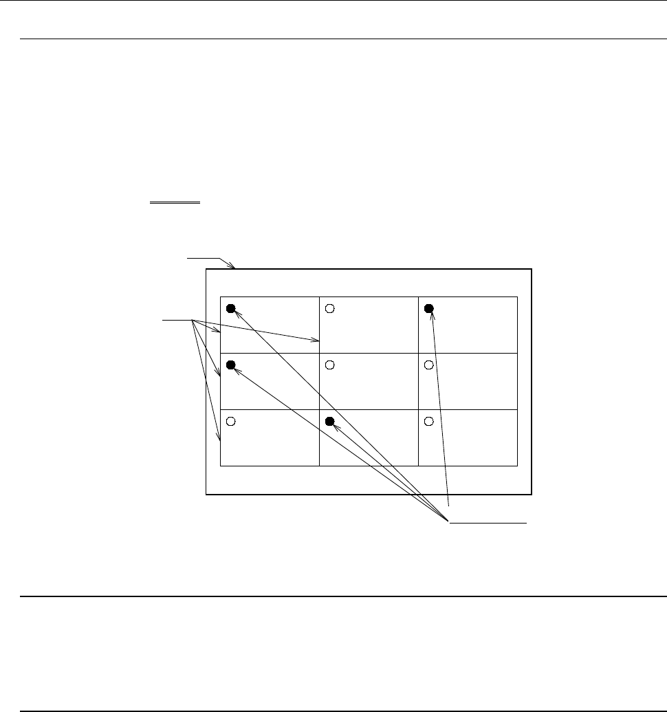
5.2.1. Bad Mark Reader (Factory-Set Option)
A bad mark is given to a circuit on a multi-circuit PWB to prevent any component from being
placed on the circuit.
The minimum diameter of a bad mark is 2.5 mm or more and the color of a mark should be
highly contrasted with the color of a board. The brightness can be switched when the color
of a board is bright (looks white).
When you use an optional bad mark reader, the time for recognizing one bad mark can be
shortened by approximately 0.1 seconds with comparing with the time taken with the
standard OCC camera.
バ ッ ド マ ー ク
グ ロ ー バ ル バ ッ ド マ ー ク
基 板
回 路
5.2.2. Feeder Changeover Function (Factory-Set Option)
This function allows a group of feeders to be attached or detached onto/from the main unit at
a time. Since this function enables changeover from the current feeders to the next feeders
even during production of PWBs, it shortens the time required for changeover.
5.2.3. Non-Stop Operation (Factory-Set Option)
This is the function for continuing PWB production without interrupting it although
components run out on the reference side when the same type of components are set on the
front side and the rear side.
PWB production is normally performed with using components set on the reference side
bank (front side or rear side) only. When components run out on the reference side, the
machine picks up components from only the opposite side bank to continue the current PWB
production. Therefore, you can replenish the machine with components even during PWB
production.
Board
Circuits
Bad marks
Figure 11
Bad marks