KE-3020_SPE_EN.pdf - 第17页
- 13 - 4.5. Applicable Compon ent 4.5.1. Applicable co mponent siz es KE - 3020 and KE - 3020R (S tandard) MNVC (Opti on) Length x W i dth Laser rec ognitio n LNC60 < S ee N ote 1 > 0.4 x 0. 2 mm t o □ 33.5 mm or L…
- 12 -
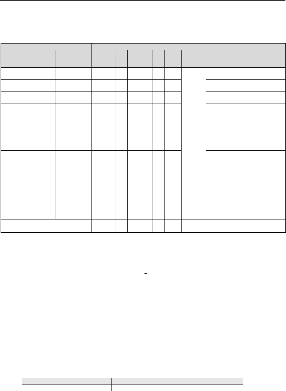
4.4. Nozzles
Various types of nozzles have been designed to increase the reliability of placement of each type
of components as shown in the table below.
You can select one of the nozzle sets shown in Table 1: as the standard nozzles supplied with
KE-3020 and KE-3020R products.
Table 1 Nozzles supplied as the standard devices
Nozzle
Nozzle assembly
Applicable components
(reference) and remarks
NO.
Internal
diameter of a
nozzle
External
diameter of a
nozzle
A B D E F G H
Std.
Nozzle
Select
500
2-φ0.4 1.0 x 0.5 − 6 − − − − −
* See
Note 1
1005, 1608, 2012 *See Note2
SOT (Molding: 1.6 x 0.8)
501
φ0.25 0.7 x 0.4 − − 6 − − −
0603
502
φ0.4 φ0.7 6 − 6 3 − − 3
1005
503
φ0.6 φ1.0 6 − 3 6 3 6 3
1608, 2012, SOT (Molding:
1.6 x 0.8), SOT (Molding: 2.0
x 1.25)
504
φ1.0 φ1.5 − 4 1 3 6 6 3
2012, 3216, SOT23, SOT
(Molding: 2.0 x 1.25)
505
φ1.7 φ3.5 1 2 − 3 3 1 3
Aluminum electrolytic capacitor
(small), tantalum electrolytic
capacitor, trimmer
506
φ3.2 φ5.0 1 1 − 1 3 1 3
Aluminum electrolytic capacitor
(medium),
SOP (narrow type),
SOJ, Connector
507
φ5.0 φ8.5 1 1 − − 1 1 1
Aluminum electrolytic capacitor
(large),
SOP (wide type),
TSOP, QFP, PLCC, Connector
508C
φ8.0 φ9.5 1 1 1 1 1 1 1
QFP, PLCC, BGA
509
φ0.1 0.4 x 0.2 − − − − − − − − 0402 only *See Note2
Total number of nozzles 16 15 17 17 17 16 17 15
* Nozzles other than the supplied ones are optional.
* Total number of nozzles that can be installed onto an ATC station: 36 pieces (Standard nozzles 34
pieces and up to large-size standard nozzles 2 pieces)
Note 1 As a Std. Nozzle Select, you can select 15 nozzles among those whose number is from 500 to 508C.
However, you have to select a nozzle to be used for calibration of the machine:
・
For laser calibration (one of the nozzles choose from 500, 502 and 503)
・
For image calibration (508C nozzle)
Note 2 Since a theta error may occur due to the shape of the surface of a 2012R component to be picked up
(such as differences of manufactures and/or resistance values), use a No. 504 nozzle if you have to
place 2012R components in the high density (the gap between the adjacent components: 0.3 mm or
less).
Note 3 To place a 0402 component on a board, not only a No. 509 nozzle but also the dedicated tape feeder
are required.
Limitation on nozzles to be used
* Limitation on nozzles used on the LNC60 of KE-3020/20R
The LNC60 head cannot be used together with a large nozzle.
* Limitation on nozzles used on the IC head side of KE-3020
The IC head of KE-3020 is intended for components of □ 3mm or more. Accordingly, the
following nozzles cannot be used because their nozzle ends are thin. (In KE-3020R,
nozzle recognition can be performed by laser, so such thin nozzles can be used.)
Nozzle No.
Standard nozzle
500, 501, 502, 503, 509
*Please contact our sales staff for an option or customized nozzle of KE-3020 IC head
(CDS).
- 13 -
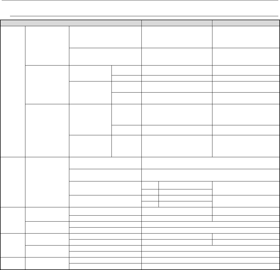
4.5. Applicable Component
4.5.1. Applicable component sizes
KE-3020 and KE-3020R (Standard)
MNVC (Option)
Length x
Width
Laser recognition
LNC60 <See Note 1 >
0.4 x 0.2 mm to □33.5 mm or
Length of a diagonal line: 47mm
FMLA (KE-3020R only)
1.0 x 0.5 mm to □33.5 mm
(33.5 mm on a side)
Vision
recognition
<See Note 2>
<See Note 9>
Standard camera
(field of vision =
54.0 mm)
Reflection
□3.0mm to □50.0mm
□
3mm to
□
33.5 mm<See Note
7>
Pass-through
□
3.0mm to
□
50.0mm
□
3.0 mm to
□
6.0 mm
Option:
highly accurate
camera (field of
vision = 27.0 mm)
Reflection
1.0mm x 0.5mm <See Note 3, 4>
to
□
24.0mm
1.0 mm × 0.5 mm <See Note 4>
to
□
20.0 mm <See Note 8>
Pass-through □3.0mm to □24.0mm □3.0 mm to □6.0 mm
Divided-image
recognition
<See Note 2>
<See Note 6>
<See Note 9>
Standard camera
(field of vision =
54.0 mm)
Reflection
Maximum 50.0 x 150.0 mm
(at 1 x 3 division);
□74.0 mm
(at 2 x 2 division)
N/A
Pass-through
Maximum 50.0 x 120.0 mm
(at 1 x 3 division)
N/A
Option:
highly accurate
camera (field of
vision = 27.0 mm)
Reflection
Maximum 24.0 x 72.0 mm
(at 1 x 3 division);
□48.0 mm
(at 2 x 2 division)
N/A
Component
height
Maximum height
differs according to
machine
specification
NC: (Max. T=12 mm)
HC: (Max. T=20 mm)
EC: (Max. T=25 mm)
LNC60
0.08 mm (for a 0402 component) to T
FMLA (KE-3020R only)
0.3 mm to T
Batch image recognition
CDS 0.4 (See Note 5) to T
0.08 to T
FMLA
0.1 to T
Divided-image recognition
CDS
0.4 (See Note 5) to T
N/A
FMLA
0.1 to T
Lead pitch
Laser
recognition
LNC60 0.65 mm or more
FMLA (KE-3020R only)
0.65 mm or more
Vision recognition
Standard camera
0.38 mm to 2.54 mm
Option
:
highly accurate camera
0.30 mm to 2.54 mm
Ball pitch
Laser
recognition
LNC60
1.0 mm to 1.27 mm
FMLA (KE-3020R only)
1.0 mm to 1.27 mm
Vision recognition
Standard camera
1.0 mm to 3.0 mm
Option
:
highly accurate camera
0.25 mm to 2.0 mm
Ball
diameter
Vision recognition
Standard camera
φ
0.4 mm to
φ
1.0 mm
Option
:
highly accurate camera
φ0.1 mm to φ0.63 mm
Note 1 The maximum size of components that can be recognized with 6 nozzles of the LNC60 at the same time is □ 10.0 mm.
When you are to place components whose size is more than □ 10.0 mm with the LNC60 head, only three heads are used to pick them up.
Note 2 The minimum dimensions of the mold should be □ 1.7 mm or more. The described maximum dimensions of a component should be
applicable if a pick-up error of the XY dimensions is ± 1 mm or less and the angle error is ± 3
°
or less.
Note 3 When the dimensions of a component are less than □ 3 mm, an NC60 head is used to recognize it and place it on a board.
Note 4 When you want to recognize image of components: a resistor chip, trimmer, SOT or LED whose size is from 1.0 × 1.0 to □ 3 mm,
recognize such a component as a general-purpose vision component.
Note 5 The minimum component height has no effect on VCS recognition but the component height shall be recognizable with a CDS
(component drop check sensor)(KE-3020 only).
Note 6 When the “Offset Placement After Solder Screen-printing” option is incorporated into KE-3020 designed for L-PWB specification (left to
right transport) and XL-PWB specification, the system cannot place a component whose diagonal line exceeds 100 mm or L-wide - PWB
on a board (if the system picks up component at its center).
Note 7 Component size
□
20 mm
~□
33.5 mm shall be available for L3 or L4 of LNC60 head only.
Note 8 Component with the size of 24.0 mm x 11.0 mm is available even though the length is more than 20mm.
Note 9 The mass of a component to be placed with the IC head is as follows:
・
Component with the size of 50 mm x 50 mm: Batch image recognition: 40g or less Divided image recognition: 35g or less
・
Component with the size of 50 mm x 150 mm: 17g or less
- 14 -
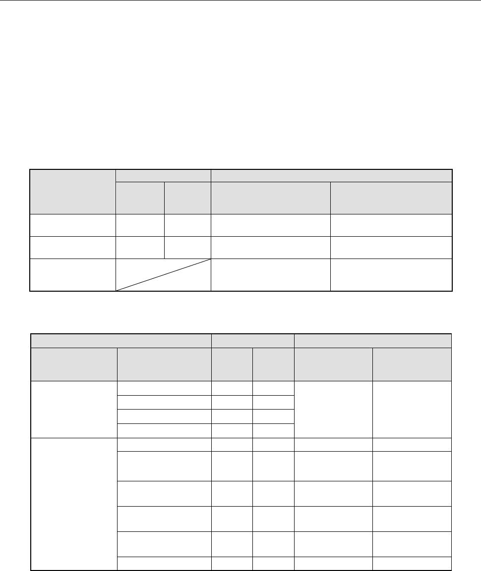
4.6. Component Placement Accuracy at X, Y and θ
*1 The regulated value of a component to be recognized with laser is “Cpk ≥ 1.”
*2 The placement accuracy that can be obtained when a placement position is corrected by
recognizing component image shall be the absolute value from the component reference
mark or PWB reference mark.
*3 The placement accuracy of a 0402 component described below is realized if local fiducial
marks are used, the distance between two marks is 20 mm or less, and a 0402
component is placed within the mark.
Placed positions (X, Y)
(Unit:μm)
Laser
Vision (VCS)
LNC60 FMLA
VCS
(when an LNC60 head is
used)
VCS
(when an IC head is used)
Square chip
0402, 0603
± 50 ― ― ―
Square chip
1005 or bigger
± 50 ± 50 ― ―
QFP
(Pitch: 0.5, 0.4, 0.3)
± 40
(When a component
positioning mark is used)
± 30
(When a component
positioning mark is used)
Placed posture (
θ
)
(Unit:°)
Laser
Vision (VCS)
Size LNC60 FMLA
VCS
(when an LNC60
head is used)
VCS
(when an IC head
is used)
Square chip
0402
±
5.0
―
― ―
0603 ±3.0 ―
1005
±
2.5
±
2.5
1608 or more
±
2.0
±
2.0
QFP
(Pitch: 0.5, 0.4, 0.3)
50 mm or more
―
―
-
±
0.04
From 40 mm to less
than 50 mm
― ― - ±0.05
From 30 mm to less
than 40 mm
― ― ± 1.11 ±0.07
From 20 mm to less
than 30 mm
― ― ±0.12 ±0.1
From 10 mm to less
than 20 mm
― ― ±0.22 ±0.2
10 mm or less
―
―
±
0.33
±
0.3
Adjacent pitch
- 0402: 0.15 mm
- 0603: 0.20 mm