KE-3020_SPE_EN.pdf - 第21页
- 17 - Figure 3 Unav ailable are as for setting up th e support pin s (Board size : L - Wide ) Note 1: When the PW B trans port d irection is rever sed (leftward flow), the unava ilable ar eas for setting up the supp ort…
- 16 -
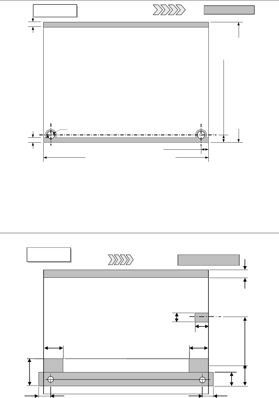
4.7.3. Unavailable areas for placing components on the board
Note 1: This is a size at shipments from the factory. Another restricted area is added when centering pin
(option) is used.
Note 2: Minimum board size becomes 50 mm when Automatic PWB transportation Width adjustment device is
attached on the machine.)
Figure 1
Unavailable areas for placing components
4.7.4. Unavailable areas for setting up the support pins
Note 1: Another restricted area is added when centering pin (option) is used.
Figure 2
Unavailable areas for setting up the support pins (Board size: L)
3 mm
3 mm
PWB
Top View
Unavailable areas
PWB
transportatio
L-PWB specification 30 to 360 mm *2
L-wide PWB specification 30 to 360 mm *2
XL-PWB specification 30 to 560 mm *2
5
±
0.1 mm
Customization 5 to 7 mm
(
(Factory-set) *1
6 mm (for pin diameter 4 mm)
5
±
0.1 mm
*1
L-PWB specification 50 to 410 mm
L-wide specification 50 to 510 mm
XL-PWB specification 50 to 610 mm
Board transportation rails fixed side
PWB
Bottom View
Unavailable areas
PWB transportation
26 mm *1
39.3mm
*1
26.5 mm *1
13 mm
26 mm *1
26.5 mm *1
20 mm
23 mm
22.6 mm
0 to187 mm
Flexible area
4.5 mm
Board transportation rails fixed side
- 17 -
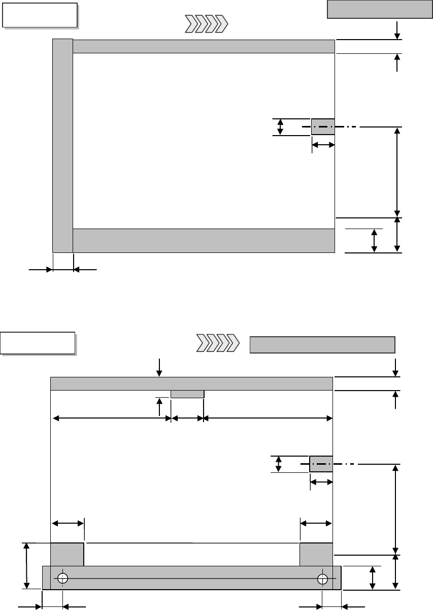
Figure 3 Unavailable areas for setting up the support pins (Board size: L-Wide)
Note 1: When the PWB transport direction is reversed (leftward flow), the unavailable areas for
setting up the support pins results in the symmetry of the left and right in the view above.
*1 Another restricted area is added when centering pin (option) is used.
Figure 4
Unavailable areas for setting up the support pins (Board size: XL)
PWB
Bottom View
Support pin Unavailable areas
PWB transportation
direction
26 mm *1
34 mm *1
26.5 mm *1
13 mm
26 mm *1
26.5 mm *1
20 mm
23 mm
22.6 mm
0 to 280.6 mm Flexible area
6.5 mm
Board transportation rails fixed side
28 mm
18.5 mm
312 mm (Right to left)
269.9 mm (Left to right)
31.1mm
20mm
23mm
22.6m
0 to187 mm
Flexible
4.5mm
Board transportation rails fixed side
13mm
PWB
Bottom View
Unavailable areas
PWB transportation
- 18 -
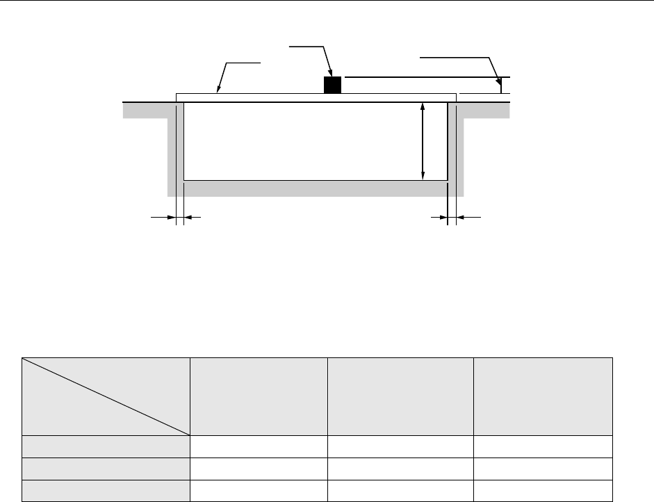
4.7.5. Area where components can be placed on the board (top and bottom)
Figure 5 Area where components can be placed on
the top and the bottom sides of a board
Maximum heights of components that can be placed (Unit: mm)
Component size
Specification
of component height
Component diagonal
less than 50 mm
Component diagonal
50 mm or more to
less than 88 mm
Component diagonal
88 mm or more
NC specification 12mm 12mm 5mm
HC specification 20mm 20mm 5mm
EC specification 25mm 20mm 5mm
PWB transportation specifications (factory-set)
L- and L-Wide PWB specifications:Front specification or rear specification
XL-PWB specifications:Front specification
PWBs clamping method
This is a method to use the PWB top surface as a reference to have both the PWB front and
rear ends each at the fixed and movable sides supported to the transport rails, then, to clamp
the PWBs.
PWB width adjusting methods
* Standard: Manually adjusting method with your hand
* Option: Automatic PWB width adjusting method via a motor
(Minimum board size: 50.0 mm x 50.0 mm)
PWB positioning reference
* Shape reference
* Pine reference (optional)
Board
Component
MAX. 40 mm
3 mm
3 mm
H: See the table
below for the dimension.