KE-3020_SPE_EN.pdf - 第57页
- 53 - 7. Contr ol Sy stem KE - 3020 and KE - 3020R adopt W indows XP as its Op er at ing Sys tem . 7.1. Control 7.1.1. Saving a pr ogram KE - 3020 and KE - 3020R mounter store a production program onto the SSD in the ma…

- 52 -
6.7.3. Options to be mounted at the factory
① Conveyor board transportation check specifications: This is a function that stops a
board on the conveyor to allow you to check it with your eyes.
(Only for a TR-6SNX, 6SXLX / TR-6DNX, 6DXLX)
② Automatic board width adjustment function: This function automatically adjusts the
width of a board to be transported in conjunction with the automatic board width
adjustment function of the mounter. (Only for a TR-6SNX, 6SXLX / TR-6DNX, 6DXLX)
③ Seesaw nozzle: This is a unit that makes the pick-up pad seesaw to prevent a
component from interfering with the pick-up pad if the surface of a component such as a
socket component to be picked up is uneven and it comes in contact with the adjacent
pick-up pad. (Only for a TR-6SNX, 6SXLX / TR-6DNX, 6DXLX)
④ Chuck for the CSP: This is a mechanical chuck that supports components such as an
FBGA whose dimensions are from □ 9 mm to □ 43 mm.
(Only for a TR-6SNX, 6SXLX / TR-6DNX, 6DXLX)
⑤ “No component” status indicating/replenishing function: The LED lights so that
you can find which tray level has no components. When you press this button, you can
replenish the tray fully.
⑥ Very slow speed mode (low speed 2): This function makes the motor and cylinder
speeds very slow to prevent any component from popping when a tray base on which
unstable components are supplied is pulled out or stored. Set the actual speed with a
production program.
⑦ Stacker equipped with the Open/Close cover: This is a stacker equipped with a cover
that eliminates difference in level to fix a tray base in order to handle components that
may easily pop when the tray base is installed on the stacker.
⑧ Signal tower wiring harness assembly: 2-lamp signal light for Non-Stop operation.
(Only for a TR-5DNX/TR-6DNX, 6DXLX)
⑨ Waffle tray holder: This is a tray holder for setting a □ 50-mm waffle tray.
⑩ RFID system: The RFID reader (antenna) is installed to read the RFID tag on a tray
base. For the use of the RFID system, the mounter needs to be applicable as well and
IFS-NX is required. For further information, refer to “IFS-NX SPECIFICATION MANUAL”.

- 53 -
7.
Control System
KE-3020 and KE-3020R adopt Windows XP as its Operating System.
7.1. Control
7.1.1. Saving a program
KE-3020 and KE-3020R mounter store a production program onto the SSD in the main unit.
When you use a USB port, you can store it on an external storage device also.
7.1.2. Limit of a production program
● Maximum number of component placement steps per circuit. : 10,000 steps
● Maximum number of circuits per PWB: 1,200 for a matrix board
200 for a non-matrix board
● Maximum number of steps per PWB: 10,000 steps
● Maximum number of component data records: maximum number of component types
that can be attached on the mounter
● Maximum number of component pick-up records: same as the above.
● Maximum number of registerable marks: 50 sets for component placement positioning
mark, 1 set for a BOC mark (2 to 3 marks)
7.2. Production Mode
The following three production modes are available during production:
PWB production
- Specifies the number of PWBs you plan to produce and produces PWBs actually.
Trial mode
- Performs a trial PWB production.
You can select the PWB pick-up position tracking function or PWB placement position
tracking function that is to be performed after placement.
Dry run mode
- Checks the PWB pick-up/placement process without using any component.
You can select the PWB pick-up/placement position tracking function.
- 54 -
8.
Other Specifications
8.1. Electrical interfaces
8.1.1. Kinds and meanings of electrical signals
The conceptual diagram of the electrical signals both on the mounters and the other side
machines is shown, as follows: The electrical signals between the mounters and
upstream-side devices ①, ② and between the mounters and downstream-side devices ③,
④ is shown in the following diagram.
a) The electrical signal ① is called the “transport request input signal (or PWBs
available-in),” receiving the PWBs transport requests from the upstream-side devices.
b) The electrical signal ② is called the “transport permit output signal (or ready-out),”
having the PWBs carried out to the upstream-side devices.
c) The electrical signal ③ is call the “transport request output signal (or PWBs
available-out),” requesting the PWBs transport to the downstream-side devices.
d) The electrical signal ④ is called the “transport permit input signal (or ready-in),
“ receiving the PWBs transport permits from the downstream-side devices.
Figure 11
Conceptual diagram connecting the electrical signal
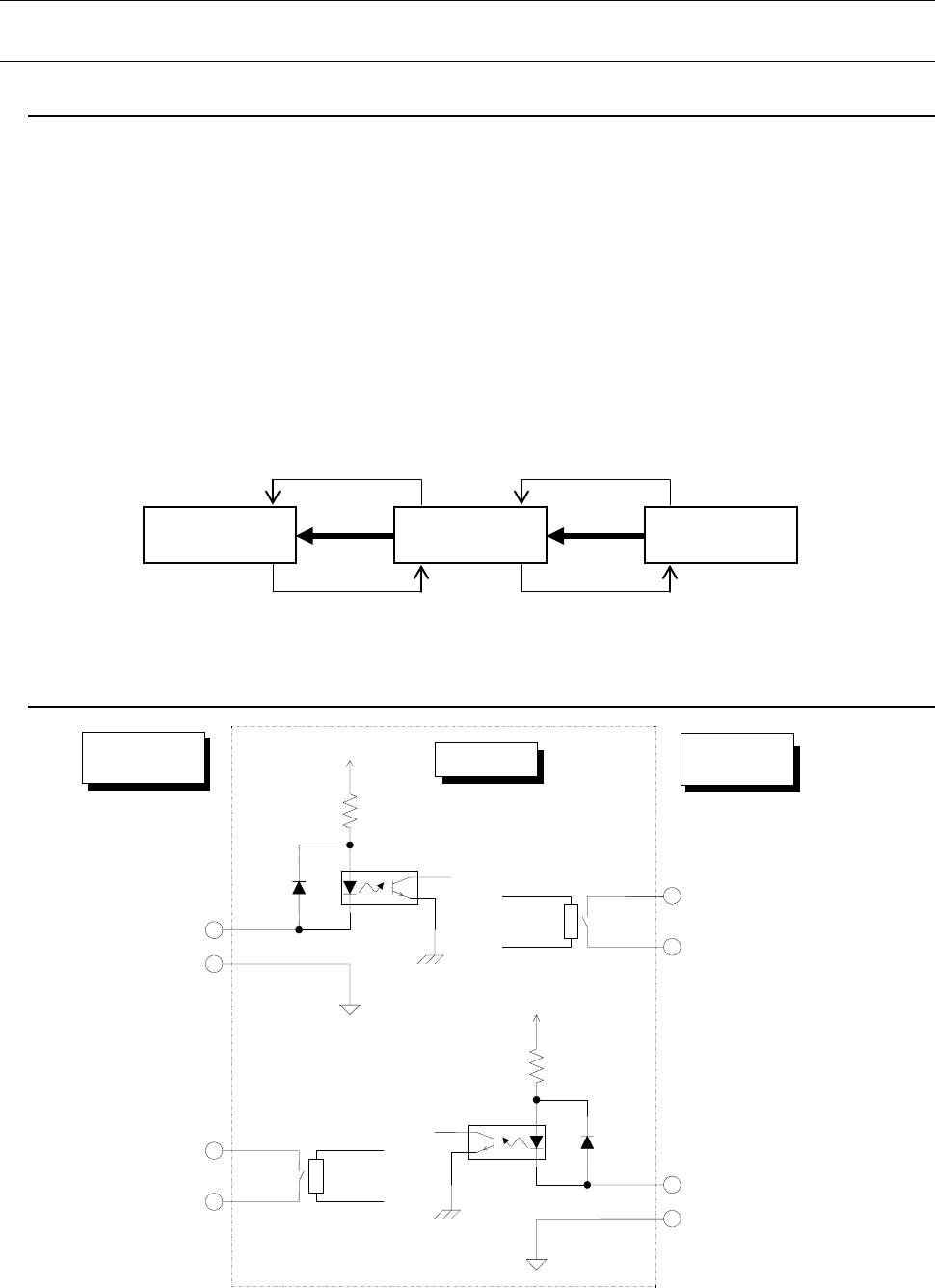
8.1.2. Specifications for connections between the front and rear devices
Figure 12
Signal interfaces and connection terminals
Downstream-
side devices
Mounters
Upstream-
side devices
④
③
②
①
Pin No. 1 :
Transport permit input signal
Pin No. 2 :
Transport permit common
signal
Relay contact
Downstream-
side devices
Mounter
Upstream-
side devices
Pin No. 3 :
Transport request output signal
Pin No. 4 :
Transport request common
signal
Pin No. 1 :
Transport permit output signal
Pin No. 2 :
Transport permit common signal
Pin No. 3 :
Transport request input signal
Pin No. 4 :
Transport request common signal
Relay contact
+24V
+24V