KE-3020_SPE_EN.pdf - 第35页
- 31 - 5.2.15. Main Line Filter ( Option to B e Installe d at the Factory ) This option prevents une xpected ingress of water into the main unit. If a trouble of the air supply device or that of the air pipe prevents dry…
- 30 -
5.2.13. Earth Leakage Circuit Breaker (Option to Be Installed at the Factory)
A standard breaker functions if any excess current flows or if a short-circuit fault occurs.
When you replace it with an earth leakage circuit breaker, this new breaker interrupts
electrical leakage, and then prevents the resulting electrical shock, so you can handle the
machine more safely..
5.2.14. Fluxer (Option to Be Installed at the Factory)
This is a flux supply device that applies flux to ball components such as a BGA, CSP and flip
chip (does not apply any adhesive or solder paste).
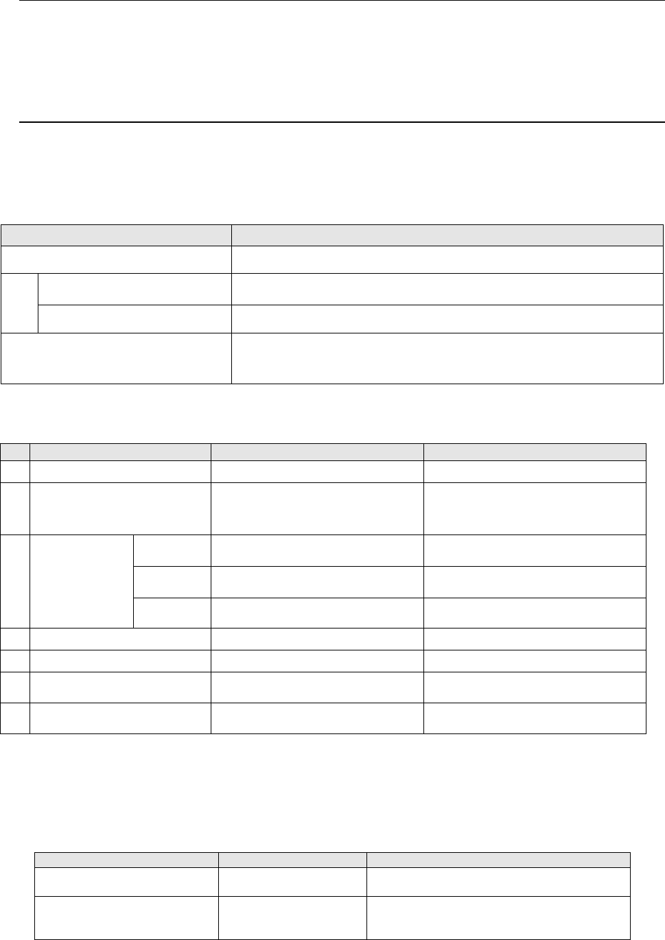
You can install this device on the mounter with either of the following two methods.
<Where to install>
Installation position
Remarks
Rear bank The number of components to be supplied onto the rear bank is restricted
Mechanical bank
The area for twelve mechanical 8-mm tape feeders is to be occupied.
(A connector bracket option is required separately.)
Electric bank The area for six electric 8-mm tape feeders is to be occupied.
Base frame
Any MTC cannot be installed on the bank at the same time.
Supply of components onto the rear bank is not restricted at all.
*The type of attached on an electric bank does not correspond to the Feeder exchange trolley RF.
<Facility specifications>
Item
Specifications
Remarks
1
Applicable flux viscosity
8.4 Pa·s to 22.0 Pa·s
2
Cycle time required for flux
application and component
placement
1,100cph
When the distance each of the X and
Y axes travels is 450 mm or less
3
Cavity
dimensions
(*See Note 3.)
Depth
Minimum 0.02 mm (± 5 μm)
Maximum 0.2 mm (± 10 %)
Size
Maximum 30 mm×30 mm
(*See Note1 and 2.)
Maximum size of a cavity when only
one cavity is provided
Number
of cavities
1 to 4
Maximum eight on the top and
bottom sides
4
Power consumption
24 VDC/0.3 A
5
Life
5 years
(22 hours×300 days)/1 year
6
Parts needing periodic
replacements
Electromagnetic valve, cylinder
Time for replacement:
2 years after use
7
Consumables
Fluxer plate, flux container
Time for replacement:
1 year after use
Note 1: The cavity size shall be “the maximum size of a component to be used” + “3-mm
margin around the component.”
Note 2: When two or more cavities are used, all cavities shall fit in the 30 mm×30 mm
area.
Note 3: If you need a cavity whose dimensions are not any of the JUKI standard
dimensions, contact our Sales person.
Standard part
Part number
Dimensions of a cavity
Fluxer plate 120/200
40044090
Size: X = 30 mm, Y = 30 mm
Depth: Front 0.12 mm/Rear 0.20 mm
Fluxer plate 30/50/70/100
40044091
Size: X = 30 mm, Y = 14 mm
Depth: Front A 0.03 mm/Front B 0.05 mm
Rear A 0.10 mm/Rear B 0.07 mm

- 31 -
5.2.15. Main Line Filter (Option to Be Installed at the Factory)
This option prevents unexpected ingress of water into the main unit.
If a trouble of the air supply device or that of the air pipe prevents dry air from being supplied
normally, this option protects the machine.
5.2.16. Ionizer (Option to Be Installed at the Factory)
This option maintains the ion balance inside the machine to eliminate static electricity and
prevent it from being generated.
This option prevents components as well as pick-up/placement operation of a component
from being damaged by static electricity to allow the machine to produce PWBs more stably.
5.2.17. IC Collection Belt (Option)
This belt collects IC components whose lead is found to be bent or float with the VCS by
separating them one by one.
You can change the feeding pitch easily by entering a value.
- Applicable component size: 10 x 10 mm to 50 x 50 mm, Height: 1 mm or higher
- Belt feeding pitch: 15 mm to 55 mm (in increments of 5 mm)
- Number of components that can be collected: 5 to 16
- Number of occupied positions: 9
5.2.18. Tape Cutter Unit (Option for the electric type of bank)
This tape cutter automatically cuts empty tapes to dispose of them in a lump.
It is an integrated type of unit that is attached onto a main unit, and can be used with a fixed
bank and also an overall feeder exchange trolley.
Power is supplied from the connector of the main unit of KE-3020 and KE-3020R.
5.2.19. Automatic Tape Cutter (Option)
This tape cutter automatically cuts empty tapes to dispose of them in a lump.
It can be combined with a floorstanding type of machine or a machine to be integrated into
an overall feeder exchange trolley.
5.2.20. Connector Bracket (Option Designed for the Fixed Bank)
This is a unit necessary for connecting devices such as an adhesive tape feeder, an IC
collection belt, an automatic tape cutter and a DTS to the mounter. When the optional batch
feeder change function is selected, you do not require this unit.

- 32 -
5.2.21. FCS (Option)
After a jig component that is recognized with the VCS or laser is placed on a glass jig board,
the Flexible Calibration System (FCS) uses a camera to automatically measure the
difference between a value set with the program and the position at which the component is
placed, and calculates the offset value to be used for placing the component.
This series of operations are automatically performed with your setting of a board and
loading of a program into the system.
When you use the FCS, you can check whether the precision is maintained and adjust the
precision at relocation or routine maintenance.
The system software is included as standard software, and if you purchase the jig parts set,
you can use this option for two or more mounters.
5.2.22. HOD (Option)
KE-3020/20R allows you to check the recognized mark image on the operation screen or
perform various teaching operations. In addition, if an experienced user of any of
conventional mounters does not want to change the operability of the mounter, or if you want
to make the operability of the entire line consistent, you can use the HOD as conventionally.
5.2.23. Software to support production (Option)
1) EPU (External Programming Unit)
This is software for creating a production program for a FX-3 on a personal computer (PC).
The screen displayed on a PC is exactly same as that of the machine. Even whil
e a
m
achine is running productions, you can edit a production program and manage
a
dat
abase on a PC with this software.
2) Flexline CAD
With this software you can convert text data files in ASCII format and production programs
created with a CAD system for other manufacture’s machines to the JUKI format. Thi
s
enables you to shorten the time to create production programs, and to more easily
transfer production programs to the JUKI production lines from others.
* For detailed information on converting data from other manufacture’s machine, please
c
ontact JUKI or the representative office in your area.
3) IS (Intelligent Shopfloor Solutions) : Production support system
In addition to the functions of HLC and SCS, IS allows you to obtain information on the
whole shop floor to optimize and manage the production collectively. This comprehensive
management system supports you to reduce cost, and to improve productivity and
product quality effectively. The ”Board viewer” function is equipped as a standard feature.
Also a production plan for a whole shop floor can be created.
*
F
or details of IS, refer to “IS PRODUCT SPECIFICATIONS”.