KE-3020_SPE_EN.pdf - 第52页
- 48 - 6.5. Stack S ti ck Feeder (for a m echanical bank) A sta ck stick feeder is to be install ed on the fixed bank, whi ch is a section of a JUKI mounter on whi ch a feeder is to be installed, or a feeder exchange tro…
- 47 -
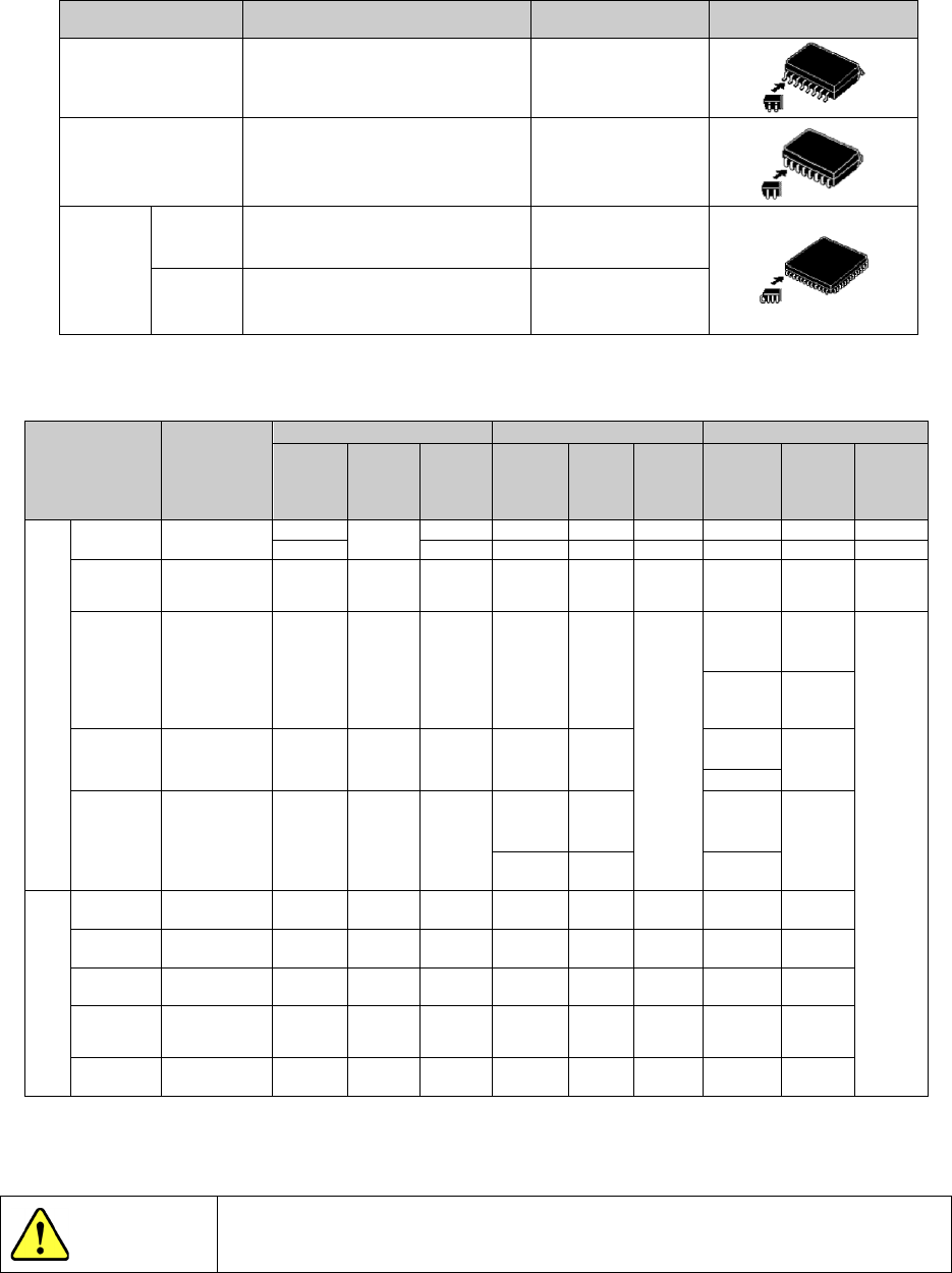
(2) Stick feeder for electric bank
An electric stick feeder is driven by the belt, which accommodates an electric bank.
It feeds an ordinary SOP, SOJ and PLCC that are packed in a stick.
* Attach the RF_ETF_ATTACHMENT when Stick feeders are used by a feeder trolley (RF)
Components Type N (SFN*EB) Type W (SFW*EB) Component shapes
SOP
(over 8 pin)
225 mil, 300 mil, 375 mil, 450 mil 525 mil, 600 mil
SOJ 300 mil, 350 mil, 400 mil, 450 mil -
QFJ
(PLCC)
Square
350 mil, 450 mil 650 mil, 750 mil,
950 mil, 1,150 mil
Rectangle
285×425 mil, 290×490 mil,
350×550 mil, 450×550 mil
-
C
all the JUKI head office or local distributor for components other than listed above.
Feeder style
Lane width
(mm)
SOP
SOJ
PLCC(QFJ)
Nominal
size
(mil)
Compo
nent
width
(mm)
Compo
nent
height
(mm)
Nominal
size
(mil)
Compo
nent
width
(mm)
Compo
nent
height
(mm)
Nominal
size
(mil)
Compo
nent
width
(mm)
Compo
nent
height
(mm)
Type N (SFN*EB)
SFN0EB *Note
225
*Note
to 1.5
-
-
-
-
-
-
300
2,0
-
-
-
-
-
-
SFN1EB 7.2 225
5.72 to
6.99
to1.5 - - - - - -
SFN2EB 9.2 300
7.62 to
8.89
2.0 300
8.38 to
8.76
3.25
to
3.76
285×425
8.05
to
8.31
4.20
to
4.57
290×490
8.13
to
8.51
SFN3EB 11.2 375
9.53 to
10.8
2.5 350
9.65 to
10.03
350×350
9.78
to
10.03
350×550
SFN4EB 13.0 450
11.43 to
12.70
3.0
400
10.92 to
11.30
450×450
12.32 to
12.57
450
12.19 to
12.57
450×550
Type W (SFW*EB)
SFW1EB 15.0 525
13.34 to
14.61
3.5 - - - - -
SFW2EB 18.2 600
15.24 to
16.51
4.0 - - - 650×650
17.40 to
17.65
SFW3EB 20.8 - - - - - - 750×750
19.94 to
20.19
SFW4EB 26.0 - - - - - - 950×950
25.02 to
25.27
SFW5EB 31.2 - - - - - -
1150×115
0
30.10 to
30.55
Note: Call the JUKI head office or local distributor for the component width of SFN0EB.
Use a stick feeder that suits the size of each component. The component
may be broken y inaccurate operation even when component is fed.
CAUTION
- 48 -
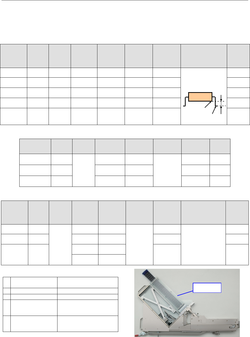
6.5. Stack Stick Feeder (for a mechanical bank)
A stack stick feeder is to be installed on the fixed bank, which is a section of a JUKI mounter
on which a feeder is to be installed, or a feeder exchange trolley, and feeds sticks of
components such as SOP, PLCC and SOJ with stacked on one another to the pick-up position
of the mounter automatically.
SOP
(
EIAJ ED-7402-1
)
Stack Stick
Feeder
type
Lane
width
( mm )
Groove
depth
( mm )
Nominal
component
size
Component
width
( mm )
Component
height
( mm )
Component
length
(
mm
)
Distance from the
bottom of a lead to
that of a mold (“A”)
(mm)
See Note 1.
Stick
width
(
mm
)
Type 1 7.0 1.7
TYPE I
225 mil
5.72 to
6.99
1.01 to
1.50
8.89 to
13.97
0.4 or less
<Note 1:
Distance “A”>
8 to 10
Type 2 9.0 2.3
TYPE
Ⅱ
300 mil
7.62 to
8.89
1.51 to
2.00
11.43 to
13.97
10 to 12
Type 3 10.8 2.8
TYPE
Ⅲ
375 mil
9.53 to
10.80
2.01 to
2.50
11.43 to
16.51
12 to 14
Type 4 12.8 3.3
TYPE
Ⅳ
450 mil
11.43 to
12.70
1.80 to
3.00
13.97 to
19.05
14 to 16
Type 5 14.8 3.8
TYPE Ⅴ
525 mil
13.34 to
14.61
3.01 to
3.50
13.97 to
24.13
16 to 18
QFJ
(
PLCC
)(
EIAJ ED-7407
)
Stack Stick
Feeder type
Lane
width
( mm )
Groove
depth
( mm )
Nominal
component
size
Component
width
( mm )
Component
height
( mm )
Component
length
(mm)
Stick
width
(mm)
Type 3L 10.8
5.1
TYPE I
350 mil
9.78 to
10.03
4.20
to
4.57
9.78 to
15.11
12 to 14
Type 4L 12.8
TYPE Ⅱ
450 mil
12.32 to
12.57
12.32 to
15.11
14 to 16
Type 6L 18.0
TYPE Ⅲ
650 mil
17.40 to
17.65
17.40 to
17.65
18 to 20
SOJ
(
EIAJ ED-7406
)
Stack Stick
Feeder
type
Lane
width
( mm )
Groove
depth
( mm )
Nominal
component
size
Component
width
( mm )
Component
height
( mm )
Component
length
(
mm
)
Distance from the
bottom of a lead to
that of a mold (“A”)
(mm)
See Note 1.
Stick
width
(
mm
)
Type 2J 9.0
4.0
TYPE I
300 mil
8.382 to
8.763
3.251
to
3.759
10.922 to
21.41
1.2 or less
10 to 12
Type 3J 10.8
TYPE
Ⅱ
350 mil
9.652 to
10.033
13.462 to
29.00
12 to 14
Type 4J 12.8
TYPE
Ⅲ
400 mil
10.922 to
11.303
17.272 to
29.00
14 to 16
TYPE
Ⅳ
450 mil
12.192 to
12.573
•
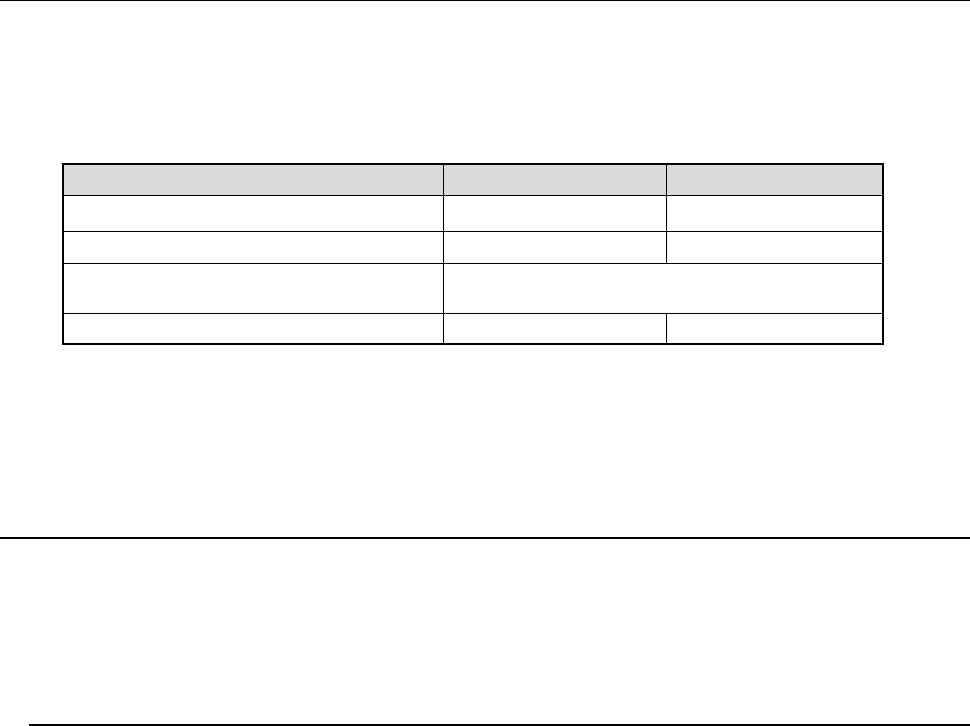
Stack Stick Feeder Specifications
1
Number of the
occupied positions
8
2
Supply voltage
DC24V
、
DC6V
3
External dimensions
8.5kg
4
Weight
Width =60mm
Height =580mm
Length =930mm
5
Dimensions of an
applicable stick
Width =20 mm or less
Height =10 mm or less
Length =400 to 600mm
Magazine
Bottom
A
- 49 -
6.6. Tray Holder
* Choose an appropriate device for the mechanical or the electric type of bank.
This tray holder is equipped with one tray, and can be installed on the rear bank so that
the head of the main unit can pick up a component directly from this holder.
When the tray size is small, several trays can be attached on the holder to allow this
holder to function as a multi-tray holder.
Full type Half type
Longitudinal direction 65 mm to 320 mm 65 mm to 155 mm
Horizontal direction 65 mm to 259.5 mm 65 mm to 259.5 mm
Thickness
5 mm to 11 mm
(from the bottom of a tray to the top of an IC)
Number of occupied positions (See Note 1)
42 21
* A number of available places at the rear side.
- Full type: 2 tray holders, - Half type: 4 tray holders
Note 1: Although the number of feeder positions actually occupied is 40 for the full type,
and 20 for the half type, the number of positions used during PWB production
(according to the feeder layout) is shown in the table above.
6.7. TR Series
TR series device supplies a mounter with a tray component.
*1 These are dedicated feeders for KE-3020 and KE-3020R. TR-**R series models that hav
e
been us
ed with conventional mounters are not supported.
*2 TR-6DXLX/6SXLX models are to be used exclusively for a mounter designed for an
XL-sized board. A mounter for L-wide board does not support MTC.
6.7.1. Overview
1) TR-1SNR/TR-1EB (DTS, Dual Tray Server)
This is a tray supply device on which two trays can be set, and is to be installed on t
he
r
ear bank so that the head of the mounter can pick up components directly from this tray
server. When you use this server in Stop mode, which supplies the same type of
components by alternately changing a tray, you can replace trays without stopping t
he
m
ain unit even though the stoked components run out.
Since the head of the mounter directly picks up components from this tray server, even
irregularly-shaped components can be supplied easily.
Note: It does not correspond to the Feeder exchange trolley RF.
2) TR-5
SNX (MTS, Matrix Tray Server)
This matrix tray server is to be installed on the rear bank of a mounter, and pulls out all
trays at a time so that the head of the mounter can pick up components directly from the
trays. Since the head of the mounter directly picks up components, ev
en
irregularly-shaped components can be supplied easily.
3) TR-5D
NX (MTS, Matrix Tray Server, Non-Stop Type)
This matrix tray server is to be installed on the rear bank of a mounter, and pulls out all
trays at a time so that the head of the mounter can pick up components directly from the
trays. Two tray stackers that control axes independently allow you to replac
e
c
omponents without stopping PWB production in Non-Stop mode even though the
stocked components run out.
Since the head of the mounter directly picks up components, even irregularly-shaped
c
omponents can be supplied easily.