KE-3020_SPE_EN.pdf - 第29页
- 25 - 5.2.6. Load control func tion (Facto ry - Set Option) W hen y ou use an optional 6*1 or 6*2 type o f nozzle, you can easily control the componen t placement load with the stroke and the spring pressure. - Load ran…
- 24 -
5.2.4. Components verification System (CVS) (Factory-Set Option)
This function is provided to inspect components to be placed before production and at the
restart after components run out, and detect errors such as component, polarity, feeder
setting position and other errors in advance. Up to six components are checked at the same
time.
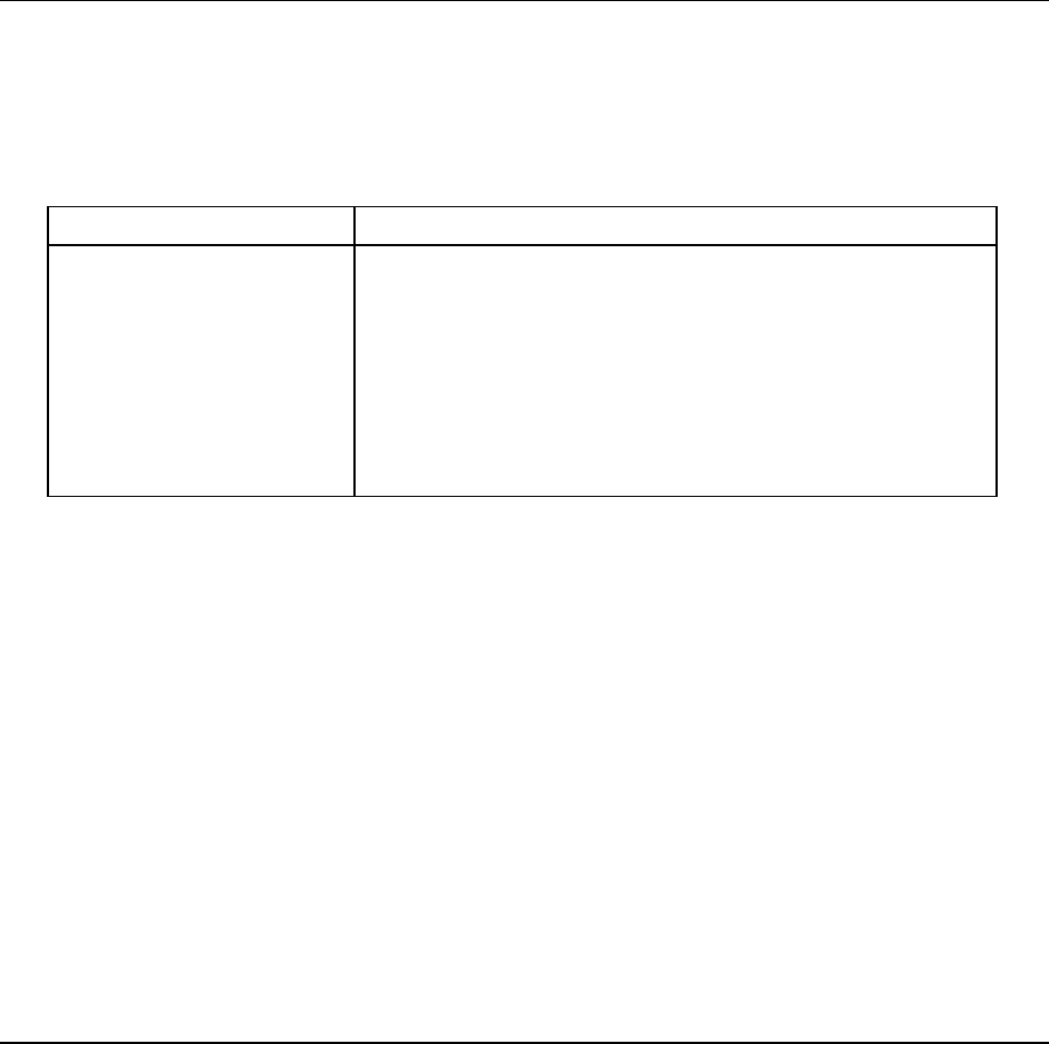
Components applicable to this check:
Applicable component type Inspection conditions
- Square chip
- Laminated ceramic
capacitor
- Tantalum chip capacitor
- Aluminum electrolytic
capacitor
- Chip film capacitor
- 2-pin diode
- Component that have two electrodes: one on the bottom
and another on the opposite side
- Component whose electrode distance is 10 mm or less
- Component whose diagonal dimensions are □ 10.00 mm or
less
- For a single measurement, small component 0402 or larger
- For simultaneous measurement, small component 1005 or
larger (The longer side shall be 0.95 mm or longer.)
* Diodes are limited to general commutating diodes (other than light-emitting diodes and
zener diodes).
Check items:
1) Resistance value Measurement range: 10 Ω to 1 MΩ
Measurement accuracy: ± 5 %
See Note 1
2) Electrostatic capacitance Measurement range:100 pF to 100 μF
Measurement accuracy: ± 20 %
See Note 1
3) Diode polarity Measurement range: Forward voltage 1.8 V or less
Open voltage 0 to 4.3 V or less
Note 1: Measurement error for a tolerance of a component
Nozzle:
A nozzle dedicated to the CVS is required to use the verification function.
5.2.5. SOT Direction Check Function (Factory-Set Option)
This function uses the left OCC to check the component supply angle by placing a 3-terminal
SOT component on the SOT direction check table before production or the restart after
components run out.
Applicable components:
- Component dimensions: 1.6 mm to 4.0 mm x 4.0 mm
- Electrode dimensions: Length 0.2 mm to 1.0 mm
Width 0.1 mm to 1.0 mm

- 25 -
5.2.6. Load control function (Factory-Set Option)
When you use an optional 6*1 or 6*2 type of nozzle, you can easily control the component
placement load with the stroke and the spring pressure.
- Load range: 6*1 type of nozzles: 98 to 135 g (1.0 to 1.32 N)
6*2 type of nozzles: 146 to 270 g (1.43 to 2.65 N)
- Precision: ± 7.5% (2N or more)
± 0.15 N (Less than 2 N)
- This function allows you to turn on or off vacuum at the same time picks up/places a
component to easily measure the load imposed during pick-up/placement of a component.
- The load profile can be displayed in the waveform.
5.2.7. Rear Side Operation Unit (Factory-Set Option)
The liquid crystal display monitor, keyboard and mouse are attached on the rear of the main
unit to secure the same efficiency as that of the front operation unit (this operation unit is
equipped with the front/rear operation switch).
5.2.8. Feeder Indicator Function (FPI) (Factory-Set Option)
This function uses LEDs to notify an operator of the feeder position to be checked if the
stocked components run out or a feeder error occurs during production of PWBs. This
feature shortens the time spent for replacing a feeder and improves the operability of the
KE-2000 series of products.
- 26 -
5.2.9. MNVC (Factory-Set Option)
This is an optional function that uses a VCS to recognize a component that is picked up by
an LNC60 head, and you can use the MNVC to perform various operations such as a
coplanarity check and recognition of a general-purpose vision component.
Use of the MNVC greatly improves the productivity of a PWB on which many small
vision-centered components are to be placed.
Applicable component dimensions
(Unit: mm)
VCS recognition with the
IC head
VCS recognition with the LNC60
head <See Notes 1 and 2.>
Length × Width
VCS
simultaneous
recognition
Standard VCS
(Field of view:
54 mm)
Reflection
□3 to □50
□3 to □33.5
Pass-through
□3 to □50
□3 to □6
Optional
high-resolution
VCS (Field of
view: 27 mm)
Reflection
□3 to □24
1.0×0.5 to □20
Pass-through
□3 to □24
□3 to □6
Note 1: Any L head cannot be used to recognize a component by dividing its image.
Note 2: The component height, lead pitch, ball pitch and ball diameter that can be recognized by the
L head are same as those that can be recognized by the R head.
Applicable nozzles
− Standard nozzles: The number. 500 to 508C nozzles are applicable. Be sure that the
number. 505, 506, 507 and 508C nozzles shall be antidazzle.
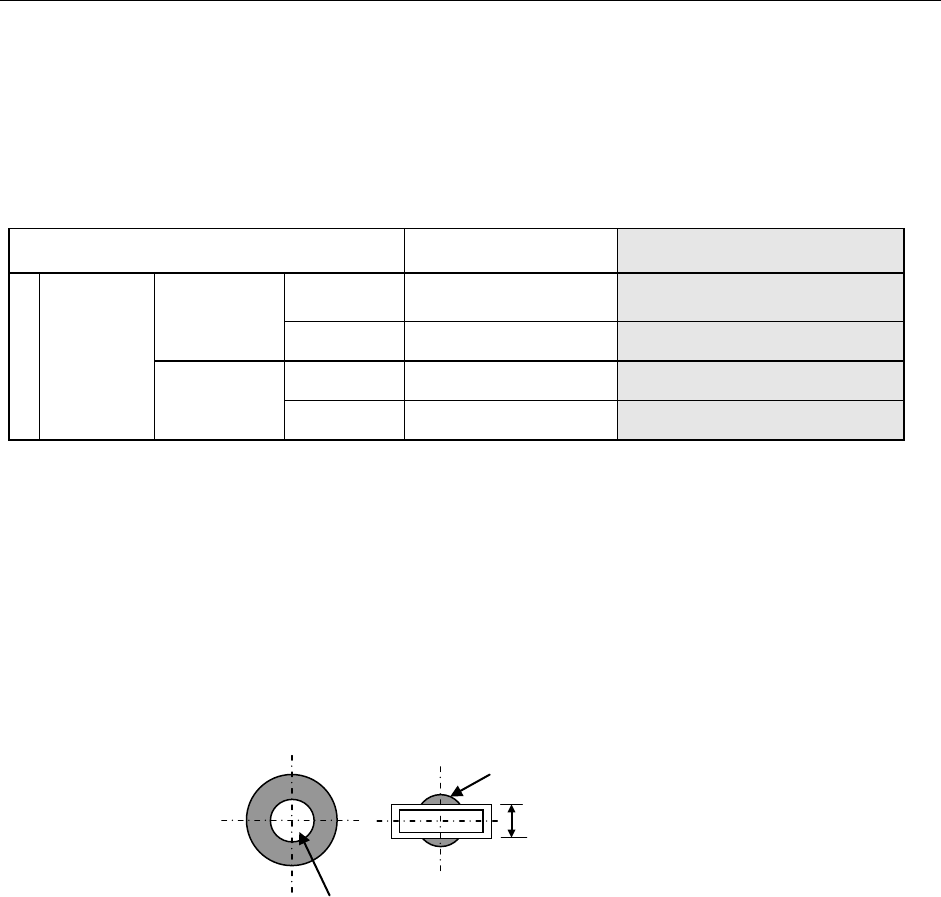
− Customized nozzles: The section of any customized nozzle that is used to pick up a
component should not gleam when it is shot with a VCS except the area ± 2.0 mm from
the center of the nozzle.
The diameter of this gleaming area should be 4 mm or smaller.
This area should not gleam.
The width should be 4 mm or narrower.