KE-3020_SPE_EN.pdf - 第13页
- 9 - 4.2. Mechanical/Electrical Spe cific ations 4.2.1. Usage envi ronment co nditions KE - 3020 / KE - 3 020R Po wer suppl y V oltag e Three - phase 200 V , 220V , 240V , 3 80V , 400 V , 415V AC ± 10% ( Se e Note 1 ) F…
- 8 -
4.
Specifications
4.1. Features of each model
① Basic specifications
KE-3020 and KE-3020R
Board specifications
L-PWB
XL-PWB
Board dimensions
Standard 410 x 360 mm 610 x 560 mm
L-Wide PWB
(Option)
510 x 360 mm -
Board transport reference position Front side or rear side Front side
Supported languages
English, Japanese, Chinese
Conveyor height
900±20mm (for Japan, China, and Southeast Asian countries)
950±20mm (for Europe and the U.S.A.)
Component height 12 mm (NC), 20 mm (HC) 25 mm (EC)
Component size
* See Note 1.
Laser recognition
0402 to □33.5 mm or Length of a diagonal line:47 mm
Image recognition
1.0 ×0.5 mm to □74 mm or 50 ×150 mm
Component
placement speed
* See Note 2 and 4
Chip component
(IPC9850)
17,100(CPH) 15,300(CPH)
IC component
* See Note 3.
5,800(CPH) 4,600(CPH)
Placement accuracy
* See Note 1.
Laser recognition
±
50
μ
m (Cpk
≧
1)
Image recognition
±30μm (±40μm for MNVC)
Number of component to be placed A maximum of 160 types(on a Electric Double Tape feeder)
EN Specifications
Enable
* Note 1: See Section 4.4 “Applicable Component” and Section 4.5 “Component Placement
Accuracy at X, Y and θ” for details of the specifications.
* Note 2: The value changes depending on the board transport reference position/height or a component
height.
* Note 3: It is the approximate value when MNVC (option) is used and/or the components are simultaneously
picked up with 6 nozzles.
*Note 4: Except case of using the RF-ETF attachment.
② The relationship among the model names, recognition devices and heads is shown below.
KE-3020
KE-3020R
LNC60
Standard
Standard
IC head (CDS)
Standard
-
IC head (FMLA)
-
Standard
VCS
Standard
Standard
MNVC
Option
Option
• LNC60 : Enables the high-speed placement of small chip components or thin
chip-shaped components with 6 nozzles on a board.
• IC head (CDS) : Enables the placement of ICs such as large QFPs, CSPs, and BGAs on a
board.
• IC head (FMLA) : Enables recognition with laser or recognition with a VCS.
An IC head (FMLA) can use all types of nozzles such as a gripper nozzle
and a customized nozzle.
• VCS : Enables the placement of IC components using image recognition on a
board. Moreover, high-resolution camera (Option) can be added to it.
• MNVC : Enables the placement using image recognition with LNC60.
Components such as small QFPs, CSPs, and BGAs can be then placed at high
speed on a board.
- 9 -
4.2. Mechanical/Electrical Specifications
4.2.1. Usage environment conditions
KE-3020 / KE-3020R
Power
supply
Voltage
Three-phase 200V, 220V, 240V, 380V, 400V, 415V AC
±10% (See Note 1)
Frequency
50/60 Hz
Rated apparent power
2.2 kVA
Air supply
Air pressure
0.5 ± 0.05 MPa dry air
Maximum air consumption
50L/min (ANR) (See Note 2)
Environment
requirements
During operation
Ambient temperature
+ 10 to + 35 °C
Placement accuracy
guarantee temperature
+ 20 to + 25 °C
Relative humidity
30 % to 80% RH (with no condensation)
Altitude
1,000m or less
During transportation or storage
Ambient temperature
- 15°C to + 70°C
Relative humidity
20 % to 95% RH (with no condensation)
Noise
75 dB (A) or less (See Note 3)
Installation conditions
(for a EN machine)
Overvoltage
category
Category III according to IEC60664-1
Pollution degree
Degree 3 according to IEC60664-1
Note 1: No power supply cable at the primary side is attached thereto.
We make NO WARRANTIES against any accident of the primary side wiring caused by
short–circuit of the power cable and so on. Please use a 5.5-mm
2
or more diameter of
power cable for each phase. (Note: the appropriate cross-section area of the cable varies
depending on the supplied power voltage and the length of the power cable.)
Cable length
(m)
Conductor cross section (mm
2
)
200Vseries 400Vseries
Less than 20 5.5 5.5
30 8.0 5.5
40
10.0
6.0
50
14.0
6.0
・
Peak current (at AC200V 3phase power) : 40A
Note 2: ANR conditions are as follows:
Temperature = 20
°
C,
Absolute pressure = 0.1MPa (=100kPa=1bar),
Relative humidity = 65%
Note 3: This value was measured with conforming to the JIS Z8731 regulation.
- 10 -
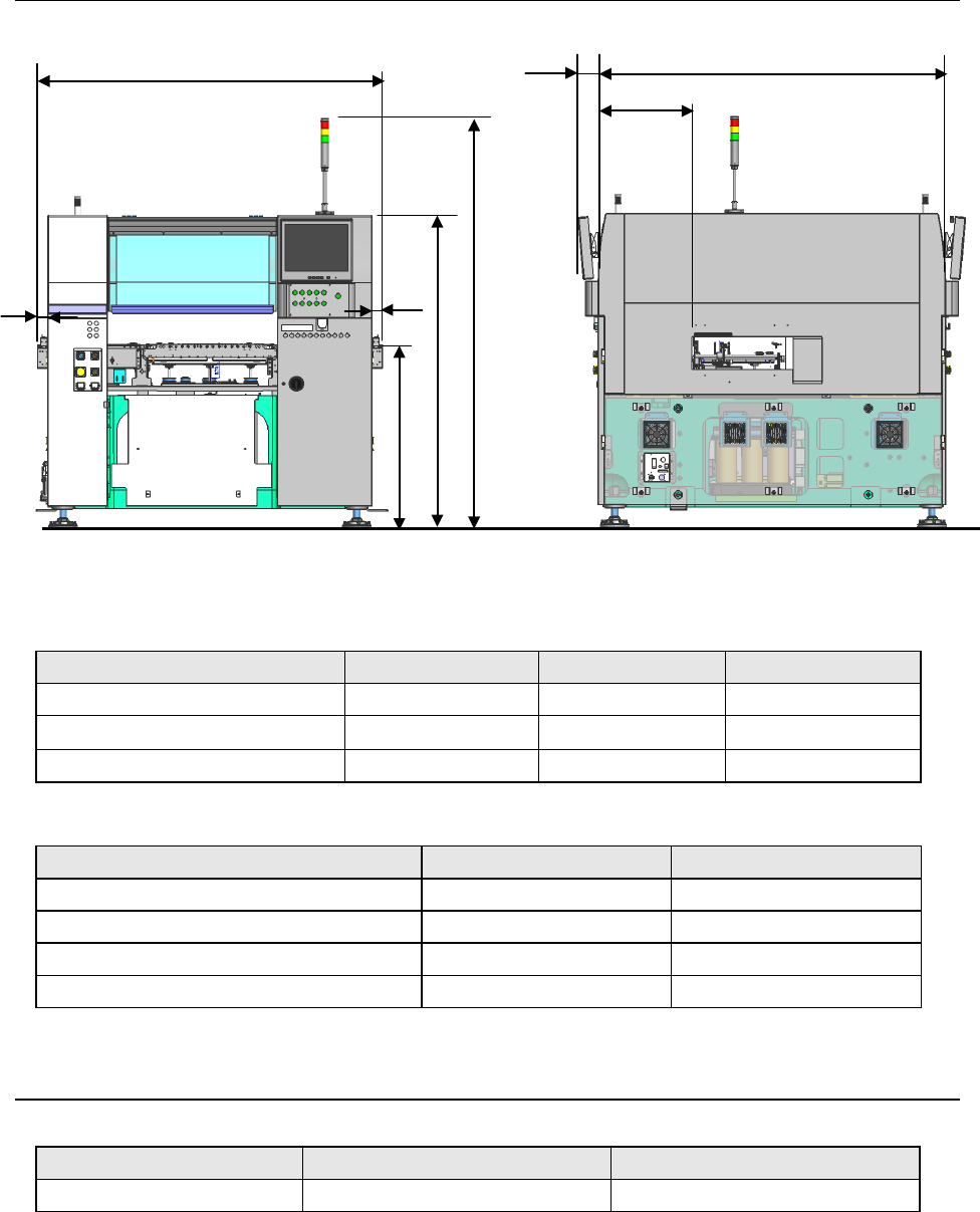
4.2.2. Outside dimension (except for the largest projections)
(Unit: mm)
Size L-PWB L-Wide-PWB XL-PWB
A (Conveyor length) 1,675 1,975 2,131
B (Excluding LCD monitors)
1,690 1,690
1,890
C (Extensions for PWB transport) 50 200 228.6(L) / 222.4(R)
(Unit: mm)
Size Transport height: 900mm Transport height: 950mm
D (Floor to top side of conveyor belt) 900 950
E (Floor to top side of cover) 1,530 1,580
F (Floor to top side of signal light) 2,000 2,050
G (Front side of cover to PWB transport rail) 484 484
4.2.3. Mass
(Unit: kg)
Model L, L-Wide PWB Specification XL-PWB Specification
KE-3020 and KE-3020R Approx. 2,100 Approx. 2,250
A
D
B
E
F
G
C
C
(100)