KE-3020_SPE_EN.pdf - 第14页
- 10 - 4.2.2. Out side dimens ion (ex cept for th e largest pr ojections ) (Unit: mm ) Size L- PWB L- Wide - PWB XL- PWB A ( Convey or length ) 1,675 1,975 2,131 B ( Excluding LCD mon itors ) 1,690 1,690 1,890 C ( Extens…
- 9 -
4.2. Mechanical/Electrical Specifications
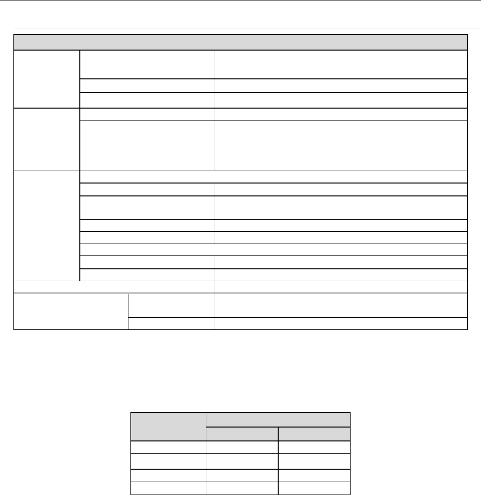
4.2.1. Usage environment conditions
KE-3020 / KE-3020R
Power
supply
Voltage
Three-phase 200V, 220V, 240V, 380V, 400V, 415V AC
±10% (See Note 1)
Frequency
50/60 Hz
Rated apparent power
2.2 kVA
Air supply
Air pressure
0.5 ± 0.05 MPa dry air
Maximum air consumption
50L/min (ANR) (See Note 2)
Environment
requirements
During operation
Ambient temperature
+ 10 to + 35 °C
Placement accuracy
guarantee temperature
+ 20 to + 25 °C
Relative humidity
30 % to 80% RH (with no condensation)
Altitude
1,000m or less
During transportation or storage
Ambient temperature
- 15°C to + 70°C
Relative humidity
20 % to 95% RH (with no condensation)
Noise
75 dB (A) or less (See Note 3)
Installation conditions
(for a EN machine)
Overvoltage
category
Category III according to IEC60664-1
Pollution degree
Degree 3 according to IEC60664-1
Note 1: No power supply cable at the primary side is attached thereto.
We make NO WARRANTIES against any accident of the primary side wiring caused by
short–circuit of the power cable and so on. Please use a 5.5-mm
2
or more diameter of
power cable for each phase. (Note: the appropriate cross-section area of the cable varies
depending on the supplied power voltage and the length of the power cable.)
Cable length
(m)
Conductor cross section (mm
2
)
200Vseries 400Vseries
Less than 20 5.5 5.5
30 8.0 5.5
40
10.0
6.0
50
14.0
6.0
・
Peak current (at AC200V 3phase power) : 40A
Note 2: ANR conditions are as follows:
Temperature = 20
°
C,
Absolute pressure = 0.1MPa (=100kPa=1bar),
Relative humidity = 65%
Note 3: This value was measured with conforming to the JIS Z8731 regulation.
- 10 -
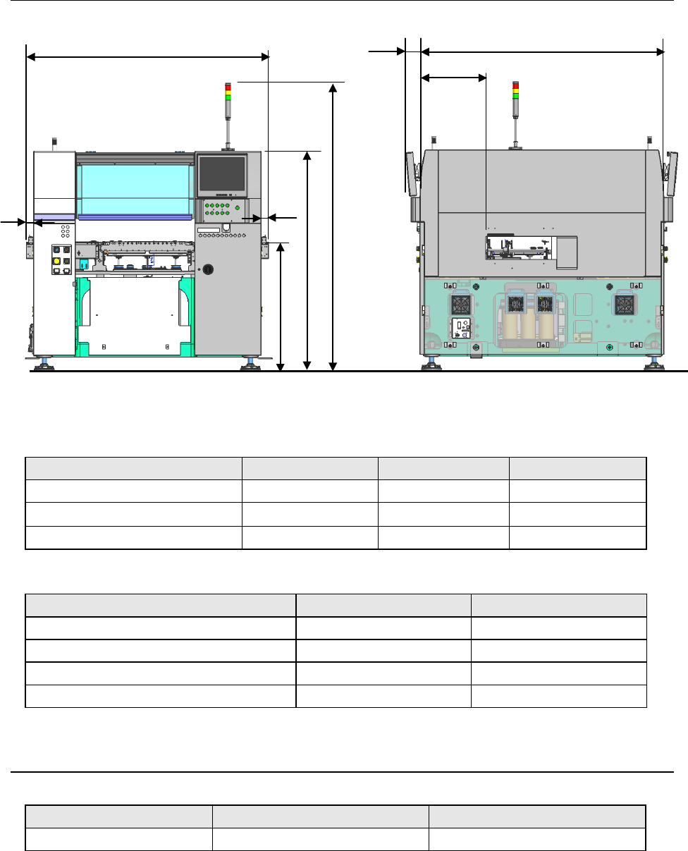
4.2.2. Outside dimension (except for the largest projections)
(Unit: mm)
Size L-PWB L-Wide-PWB XL-PWB
A (Conveyor length) 1,675 1,975 2,131
B (Excluding LCD monitors)
1,690 1,690
1,890
C (Extensions for PWB transport) 50 200 228.6(L) / 222.4(R)
(Unit: mm)
Size Transport height: 900mm Transport height: 950mm
D (Floor to top side of conveyor belt) 900 950
E (Floor to top side of cover) 1,530 1,580
F (Floor to top side of signal light) 2,000 2,050
G (Front side of cover to PWB transport rail) 484 484
4.2.3. Mass
(Unit: kg)
Model L, L-Wide PWB Specification XL-PWB Specification
KE-3020 and KE-3020R Approx. 2,100 Approx. 2,250
A
D
B
E
F
G
C
C
(100)
- 11 -
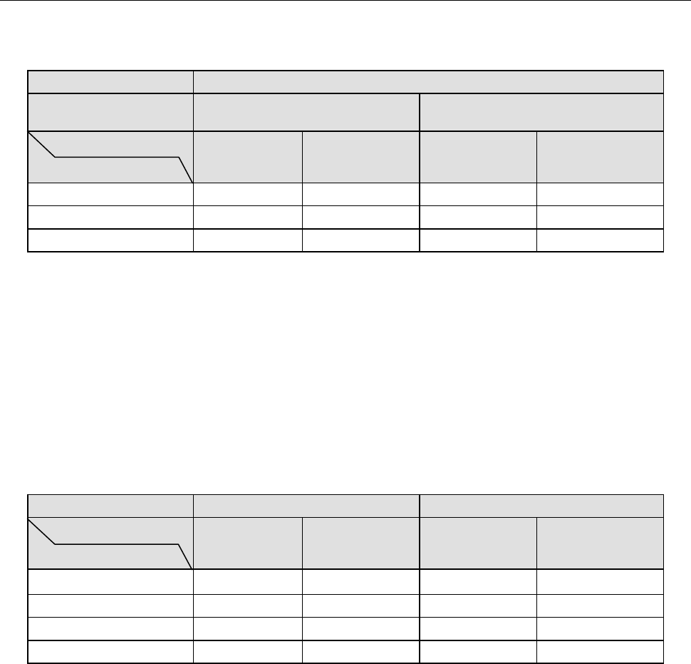
4.3. Component placement Cycle Time
(The Number of Component to Be Placed Per Hour)
① Laser recognition
(Unit: CPH)
KE-3020 and KE-3020R
Board transport
reference position
Front side Rear side
Board specifications
Component height
L, L-Wide XL L, L-Wide XL
12 mm 17,100 - 15,000 -
20 mm 15,900 - 14,000 -
25 mm - 15,300 - -
*1: This is the number of components to be placed for one hour when 400 pieces of 0603 and 1005 capacitors
are placed onto a 200 mm x 200 mm board at an angle of 0, 90, 180 and 270 degrees sequentially. (This
method conforms to the IPC9850 regulation.)
*2: Electric feeders are used as a component supply device.
*3: KE-3020 and KE-3020R place components in sequence by simultaneous pick-up of the 6 nozzles of the
LNC60 head.
*4: Since the 0402 components require to be placed in the particular sequence, when only the 0402
components are placed the placement cycle time is reduced to approximately half.
*5: For the rear reference, each value indicates the cycle time to be applied when components are placed from
a tape feeder attached on the front side.
② Image recognition
(Unit: CPH)
Used head MNVC 6 heads (Optional) IC head
Board specifications
Component supply device
L, L-Wide XL L, L-Wide XL
Tape feeder 5,800 4,600 - -
TR-1SNR 4,300 3,500 2,200 2,000
TR-5SNX 3,400 3,000 2,100 1,800
TR-6SXLX/ 6SXLX 1,200 1,100 1,300 1,100
*1: This is the number of components to be placed for one hour when 36 pieces of QFP and BGA whose outer
dimension is 10 mm x 10 mm or less are placed onto a 330 mm x 250 mm board at an angle of 0, 90, 180
and 270 degrees sequentially.
*2: For a tape feeder, it indicates the placement cycle time to be applicable when lead components whose outer
dimensions are 10 mm x 10 mm or less are placed from a tape feeder attached on the rear side.
*3: Component height is 12 mm for L and L-Wide machine.
*4: The time for ATC replacement, board transport and BOC mark recognition is excluded.