KE-3020_SPE_EN.pdf - 第30页
- 26 - 5.2.9. MNVC (Facto ry - Set Opt ion) This is an optional function tha t us es a V CS to recognize a component that is pic k ed up by an LNC60 head, and you can use the MNVC to perform various operations such as a …

- 25 -
5.2.6. Load control function (Factory-Set Option)
When you use an optional 6*1 or 6*2 type of nozzle, you can easily control the component
placement load with the stroke and the spring pressure.
- Load range: 6*1 type of nozzles: 98 to 135 g (1.0 to 1.32 N)
6*2 type of nozzles: 146 to 270 g (1.43 to 2.65 N)
- Precision: ± 7.5% (2N or more)
± 0.15 N (Less than 2 N)
- This function allows you to turn on or off vacuum at the same time picks up/places a
component to easily measure the load imposed during pick-up/placement of a component.
- The load profile can be displayed in the waveform.
5.2.7. Rear Side Operation Unit (Factory-Set Option)
The liquid crystal display monitor, keyboard and mouse are attached on the rear of the main
unit to secure the same efficiency as that of the front operation unit (this operation unit is
equipped with the front/rear operation switch).
5.2.8. Feeder Indicator Function (FPI) (Factory-Set Option)
This function uses LEDs to notify an operator of the feeder position to be checked if the
stocked components run out or a feeder error occurs during production of PWBs. This
feature shortens the time spent for replacing a feeder and improves the operability of the
KE-2000 series of products.
- 26 -
5.2.9. MNVC (Factory-Set Option)
This is an optional function that uses a VCS to recognize a component that is picked up by
an LNC60 head, and you can use the MNVC to perform various operations such as a
coplanarity check and recognition of a general-purpose vision component.
Use of the MNVC greatly improves the productivity of a PWB on which many small
vision-centered components are to be placed.
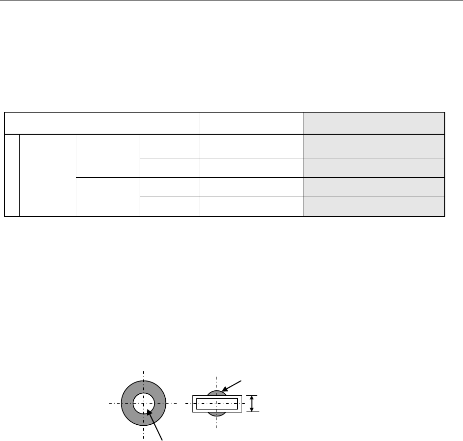
Applicable component dimensions
(Unit: mm)
VCS recognition with the
IC head
VCS recognition with the LNC60
head <See Notes 1 and 2.>
Length × Width
VCS
simultaneous
recognition
Standard VCS
(Field of view:
54 mm)
Reflection
□3 to □50
□3 to □33.5
Pass-through
□3 to □50
□3 to □6
Optional
high-resolution
VCS (Field of
view: 27 mm)
Reflection
□3 to □24
1.0×0.5 to □20
Pass-through
□3 to □24
□3 to □6
Note 1: Any L head cannot be used to recognize a component by dividing its image.
Note 2: The component height, lead pitch, ball pitch and ball diameter that can be recognized by the
L head are same as those that can be recognized by the R head.
Applicable nozzles
− Standard nozzles: The number. 500 to 508C nozzles are applicable. Be sure that the
number. 505, 506, 507 and 508C nozzles shall be antidazzle.
− Customized nozzles: The section of any customized nozzle that is used to pick up a
component should not gleam when it is shot with a VCS except the area ± 2.0 mm from
the center of the nozzle.
The diameter of this gleaming area should be 4 mm or smaller.
This area should not gleam.
The width should be 4 mm or narrower.
- 27 -
5.2.10. High resolution camera (Factory-Set Option)
When a line unit that permits switching between reflection and transmission recognition and
switching among wavelengths (red, blue, and green) is combined, fine-pitch components
(leads and balls) that cannot be recognized by standard camera can be recognized.
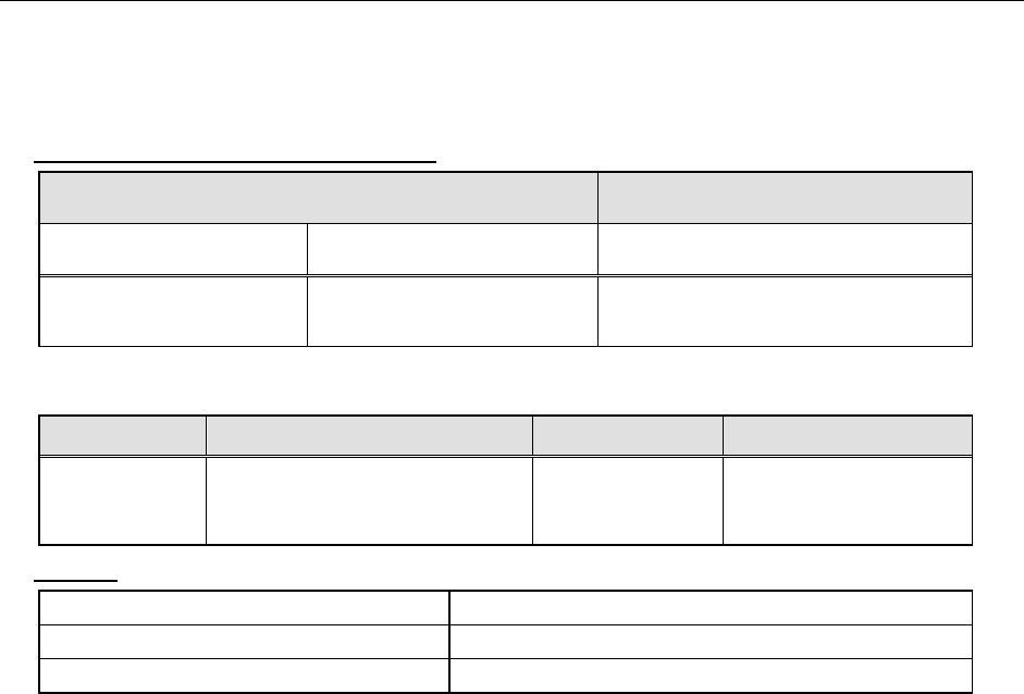
Dimensions of applicable components (Unit: mm)
VCS batch recognition VCS Divided-image recognition
(IC head only)
Reflected-light recognition
component
Pass-through-light recognition
component
Reflected-light recognition component
MNVC: 1.0 x 0.5 to □ 20.0
IC head: □3 to □24.0
MNVC: □ 3.0 to □ 6.0
IC head: □3.0 to □ 24.0
Maximum: 24.0 x 72.0 (at 1x3 division)
□48.0 (at 2x2 division)
* Even though the dimensions exceed □ 20 mm, 24 mm×11 mm is acceptable.
Lead pitch Component height Ball pitch Ball diameter
0.3 to 2.54
- NC specification 0.08 to 12.0
- HC specification 0.08 to 20.0
- EC specification 0.08 to 25.0
0.25 to 2.0 φ0.10 toφ0.63
Lighting
Lead components reflection lighting Coaxial, downward and sideward lighting via red LEDs
Area array components sideward lighting Ball sideward lighting via blue LEDs
Pass-through lighting Profile pass-through lighting via green LEDs
* Adjusting the lighting intensity can be made per component.