KE-3020_SPE_EN.pdf - 第9页
- 5 - High Maintainability ① The maintainability has been enhanced by displaying the screens of pic k - up frequencies per nozzle and o f X/Y axis traveling distances to call a chec k ing time, in addi tion t o the hour …

- 4 -
Versatility
① For KE-3020 and KE-3020R, the component recognition system which has the switchover
between the reflection and pass-through illuminance control, waveform (color) switching
and coaxial light functions improves the QFP, BGA and CSP recognition capability and the
handling capability of irregularly-shaped components such as a connector.
② A high-resolution camera can be added thereto as an option, in addition to a standard
component recognition camera (maximum component size = is 50 mm×150 mm or □74
mm).
③ As a lighting unit that permits light quantity adjustment under software control is used,
resulted in enhancing both recognizing the marks on the flexible PWBs and the same via
the pattern matching function. The function of recognizing the area marks also made it
possible to place a multiple number of components upon a set of mark corrections.
④ A bad mark indicating a defective circuit can be detected with an OCC or a dedicated bad
mark reader (option). Moreover, the recognition time can be reduced with "Extension bad
mark" function that can freely set the mark position.
⑤ The components can be picked up and placed under a certain amount of load by adopting
a load calibration station (load cell) and a load control nozzle. (Option)
⑥ The main unit of KE-3020/3020R is equipped with three types of banks: “mechanical
feeder bank,” “electric feeder bank” and “bank for both a mechanical feeder and an
electric feeder) (available with a mounter that is designed to be used with a feeder trolley
only).” The existing mechanical tape feeders, bulk feeders, and stick feeders can be
used continuously.
⑦ A new type Component Verification System (CVS) that prevents a component from being
set at a wrong position is provided. It can check a minute component such as a 0402
component, and can check up to six components at the same time if their size is larger
than or equal to that of a 1005 component. This feature shortens the checking time.
High Flexibility
① Program data created with a conventional CX, FX or KE-series mounter can be loaded to
these mounters.
② Combination with the production support system allows you to create a production line
including an existing mounter model and to create a production program for the entire line
with the client side of production support system.
③ An idle transport can be operated at a state of freeing the servomotors for heads and
client X/Y axis.
Operability
① Displaying the graphics in rich facilitated an ease of operating the data inputs
② Key operations can be made easier by using a touch panel.
③ Provided with an option of feeder position indicator (FPI), the stocked components run out
or warns that the number of the remaining components is below the regulated number
with lighting the corresponding LED. This feature indicates which feeder is to be
replaced. (Option)
④ The display is made in the language of the delivery destination (Japanese or Chinese)
and can be switched over to English display.
⑤ Installing a USB port permits using a memory unit such as USB flash memory.
This allows you to move a production program more easily.
⑥ The database sharing with two or more machines becomes possible by enabling the external
PC to edit the "Component database" that recorded data for the sizes of components and the
vision recognition data.

- 5 -
High Maintainability
① The maintainability has been enhanced by displaying the screens of pick-up frequencies
per nozzle and of X/Y axis traveling distances to call a checking time, in addition to the
hour meter (energized hours).
② Protecting the passwords has hierarchically stratified the maintenance levels to increase
a degree of freedom in setting the machines.
③ A head filter is installed in the upper part of the head to facilitate replacement.
Response to the safety standards
① The machine marked with Europe CE directive is added to the line-up.
Environment and energy saving
① Power consumption has been reduced by 25% by adopting AC servomotor and ball screw
control for the axis control compared with the former machine. The energy efficiency has been
thus improved. (Compared with KE-2080)
- 6 -
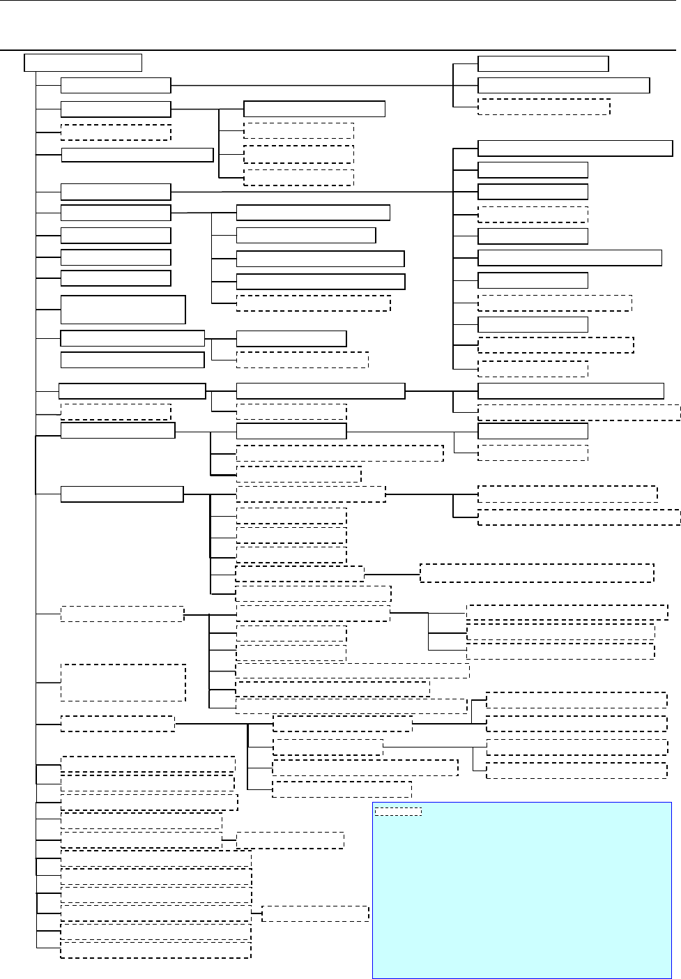
3.
System Configuration
3.1. KE-3020 System Configuration
Power unit
Cabinet
Emergency stop button
ATX power supply (with UPS function)
Leakage breaker *1
CPU
Liquid crystal display (Touch panel)
Mouse
HOD
SSD
Communication port (Ethernet board)
Touch panel
Rear side operation unit *1
DVD/CD-ROM drive (USB)
FD drive (USB)
Keyboard
USB port
Signal tower with the buzzer
Mini signal light *1
I/O control CPU
Motor control unit
X-Y control unit
Placing head
Laser recognition head (LNC60)
IC head (CDS)
Offset Correction Camera (OCC) L,R
Height Measurement System (HMS)
Bad Mark Reader (BMR) *1
Vacuum pump
Main line filter *1
Automatic PWB transportation Width adjustment device
Pin reference *1
L-Wide *1, *3
Feeder float detecting function
SOT direction check function *1
Components Verification System (CVS)
*1
Feeder position indicator function (FPI) *1
Flexible Calibration System (FCS)
External Programming Unit (EPU)
Intelligent Shopfloor Solutions (IS)
Intelli Stocker *2
Connector bracket *1
Trash box
Intelli feeder trolley for mechanical feeder *2
Tape feeder, Bulk feeder, Stick feeder *2
IC collection belt
Tape cutter unit *1
Component supply unit Tape feeder, Stick feeder *2
Tray feed device
MTC
(
TR-6DNX/6DXLX, 6SNX/6SXLX
)
MTS (TR-5DNX/SNX)
DTS (Dual Tray Server)
Tray holder
Super Foot *1
Caster *1
*3
MNVC *1
High-resolution camera (vision field: 27 mm) *1
IC collection belt
Feeder trolley for electric feeder(EF)/(RF)*7
Intelli feeder trolley for electric feeder *2
TR-1SNR for mechanical feeder bank
TR-1EB for electric feeder bank
Tray holder for mechanical feeder bank
Tray holder for electric feeder bank
Coplanarity function
*1
Load calibration stage *1
Offset Placement After Solder Screen-printing *1
KE-3020
Ionizer
*1
Component DB function*4
Mechanical feeder bank
Automatic Tool Changer
(ATC)
Air pressure unit piping system
Load control nozzle
Placement station
PWB conveyor unit
Outline reference
VCS camera
Standard camera (vision field: 54
mm)
Feeder trolley for mechanical feeder
Batch feeder change function *1
Batch feeder change function *1
Electric feeder bank *1
Vision Centering System(VCS)
Component supply unit
Fluxer *1
Feeder bank for both a
mechanical feeder and an
electric feeder *1 *5
Tape reel attaching platform
ETF Tape reel attaching platform(EF)/(RF)
RF-ETF attachment *6
Production support system (IS Lite,JaNets)
Production management system (IFS-NX)
Equipment or a function surrounded by a dashed line is optional.
*1 An option indicated with an asterisk "*" is to be mounted on the main unit at
the factory.
*2 To use the production management system, Applicable to FRID is required.
(factory-set option).
*3 It is available for only machines handling L-PWB.
*4 Another PC is necessary to use Component DB function.
*5 See the description of each feeder bank for an option to be shared (only the
function for a feeder exchange trolley is supported).
*6 Attach this component when electric feeders are used by a feeder trolley
(RF).(If you use the EF series electric feeder attachment, non-teaching and
synchronous adsorption guarantee are excluded.)
*7 It's necessary to change the cutter unit to the latest to use "Feeder exchange
trolley RF".
Offline power supply for an electric bank (PW01/02)