KE-3020_SPE_EN.pdf - 第20页
- 16 - 4.7.3. Unavailabl e areas for placing c omponents on the boar d Note 1: This is a size at shipm ents from t he factory . A nother restri cted area is add ed when center ing pin (option) i s used. Note 2: Minimum b…
- 15 -
4.7. Applicable PWBs
4.7.1. PWBs transport direction
Rightward flow (transporting from left to right, looking from the front side)
Leftward flow (transporting from right to left, looking from the front side)
Note
:
This direction is set at the factory (Factory-set).
4.7.2. PWB sizes and Mass
1) PWB sizes
(Unit: mm)
Minimum size (L
1
x W
1
)
<See Note 1>
Maximum size (L
2
x W
2
)
<See Note 1>
Thickness T
L-PWB specification
50.0 x 30.0
(With function of automatically
adjusting the PWB width:
50.0 x 50.0)
410.0
×
360.0
0.3 to 4.0
L-Wide specification
510.0×360.0
XL-PWB specification
610.0×560.0
Note 1: “L” indicates the dimension in the board transport direction, and “W” indicates the direction
perpendicular with “L.” W/L should be 2 or less.
Note 2: Contact us for a notched board or board whose shape is irregular.
Note 3: A PWB whose reflection ratio is low may not be able to be detected regardless of its material
or color.
2) Maximum allowance of PWB mass :2,000 g
3) Allowable warpage of a PWB
0.2 mm or less per 50 mm area, and 1 mm or less for both upper and lower directions
(these values conform to the JIS B 8461 regulation.)
- 16 -
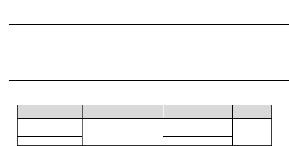
4.7.3. Unavailable areas for placing components on the board
Note 1: This is a size at shipments from the factory. Another restricted area is added when centering pin
(option) is used.
Note 2: Minimum board size becomes 50 mm when Automatic PWB transportation Width adjustment device is
attached on the machine.)
Figure 1
Unavailable areas for placing components
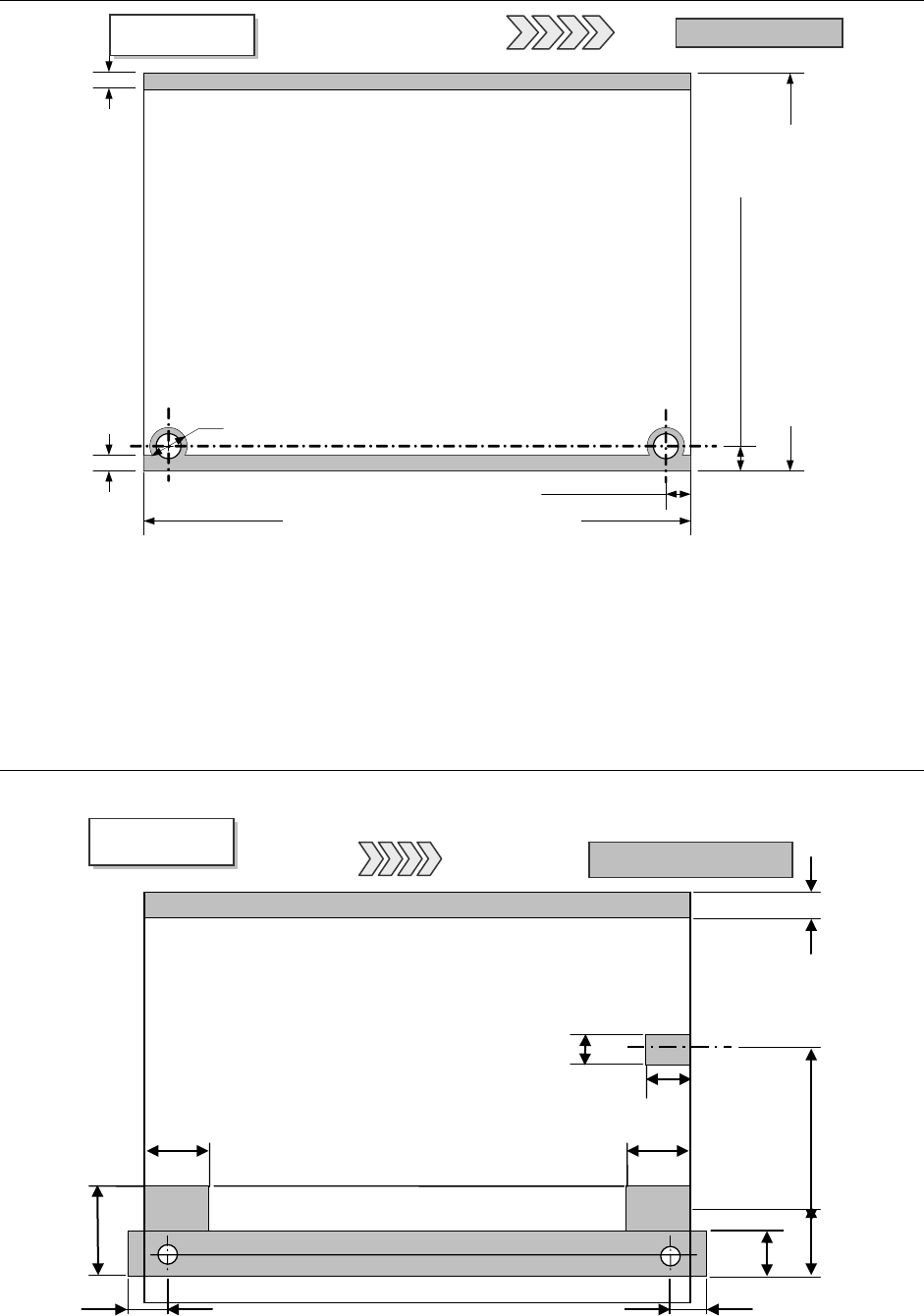
4.7.4. Unavailable areas for setting up the support pins
Note 1: Another restricted area is added when centering pin (option) is used.
Figure 2
Unavailable areas for setting up the support pins (Board size: L)
3 mm
3 mm
PWB
Top View
Unavailable areas
PWB
transportatio
L-PWB specification 30 to 360 mm *2
L-wide PWB specification 30 to 360 mm *2
XL-PWB specification 30 to 560 mm *2
5
±
0.1 mm
Customization 5 to 7 mm
(
(Factory-set) *1
6 mm (for pin diameter 4 mm)
5
±
0.1 mm
*1
L-PWB specification 50 to 410 mm
L-wide specification 50 to 510 mm
XL-PWB specification 50 to 610 mm
Board transportation rails fixed side
PWB
Bottom View
Unavailable areas
PWB transportation
26 mm *1
39.3mm
*1
26.5 mm *1
13 mm
26 mm *1
26.5 mm *1
20 mm
23 mm
22.6 mm
0 to187 mm
Flexible area
4.5 mm
Board transportation rails fixed side
- 17 -
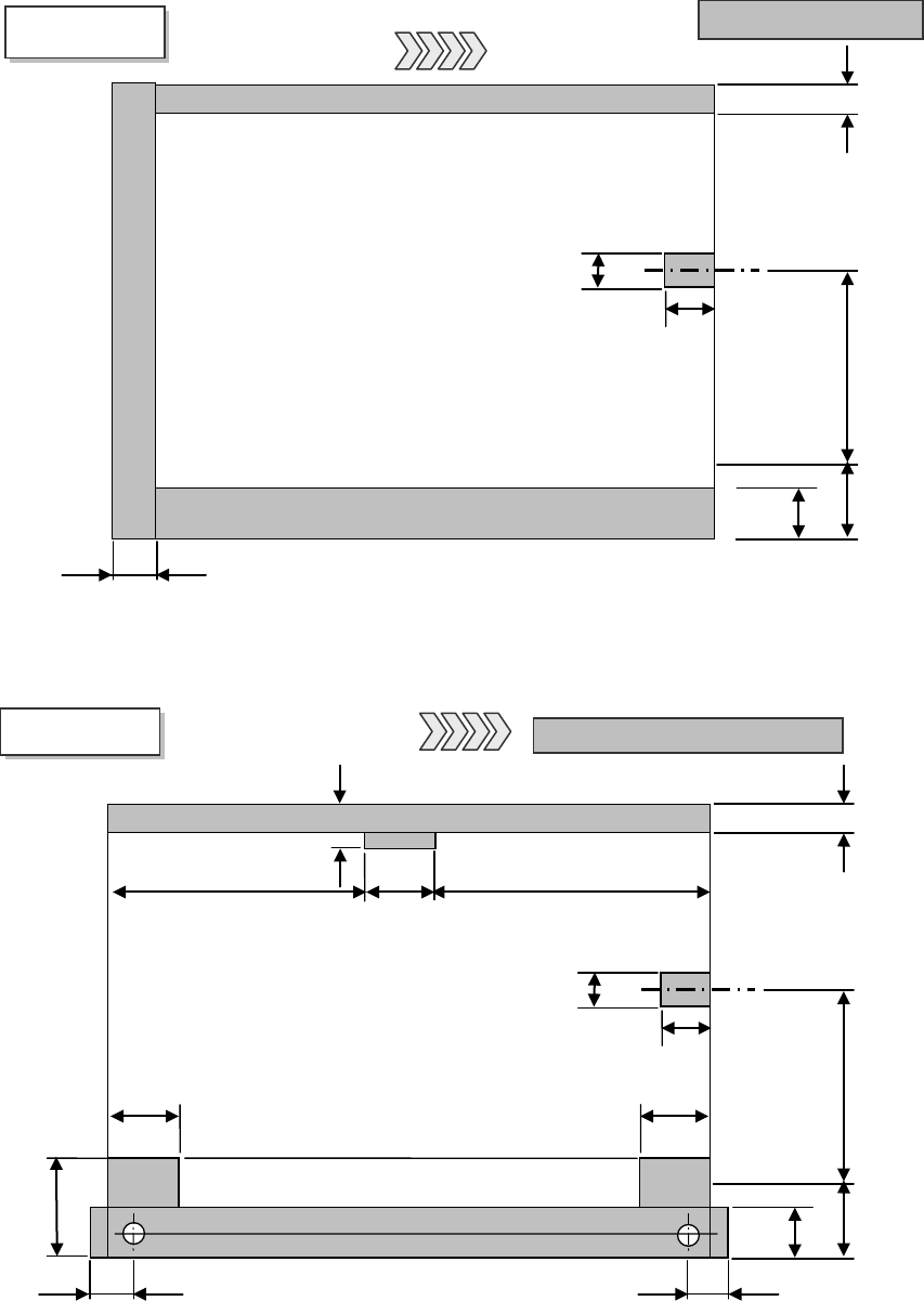
Figure 3 Unavailable areas for setting up the support pins (Board size: L-Wide)
Note 1: When the PWB transport direction is reversed (leftward flow), the unavailable areas for
setting up the support pins results in the symmetry of the left and right in the view above.
*1 Another restricted area is added when centering pin (option) is used.
Figure 4
Unavailable areas for setting up the support pins (Board size: XL)
PWB
Bottom View
Support pin Unavailable areas
PWB transportation
direction
26 mm *1
34 mm *1
26.5 mm *1
13 mm
26 mm *1
26.5 mm *1
20 mm
23 mm
22.6 mm
0 to 280.6 mm Flexible area
6.5 mm
Board transportation rails fixed side
28 mm
18.5 mm
312 mm (Right to left)
269.9 mm (Left to right)
31.1mm
20mm
23mm
22.6m
0 to187 mm
Flexible
4.5mm
Board transportation rails fixed side
13mm
PWB
Bottom View
Unavailable areas
PWB transportation