KE-3020_SPE_EN.pdf - 第25页
- 21 - Dimensions and tol erances The outside dimensions shall range from 0.5 mm up to 3.0mm, whose tolerance, less than 10%. For all the inside - blank forms, the ed g ing line w idth shall be more than 0.2 m m. Figur e…
- 20 -
搭 載 グ ル ー プ
エ リ ア 部 品 位 置 決 め マ ー ク
部 品 位 置 決 め マ ー ク
基 準 マ ー ク
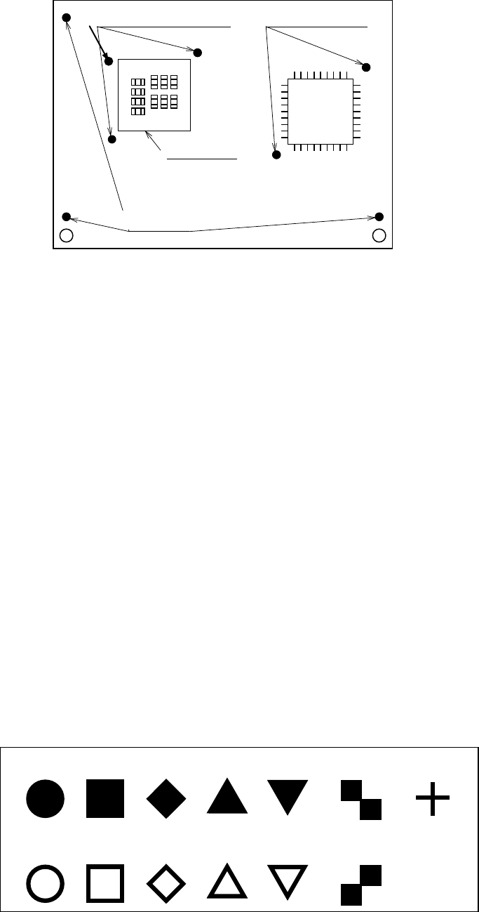
Figure 7 Reference marks and components positioning marks
Basic quality of recognition marks
- Copper not coated or coated
- It needs to have a clear contrast between the recognition mark surface and the print
wiring quality.
- It needs to have neither oxidation nor quality deterioration of the recognition marks.
Coating the recognition marks
The recognition mark surfaces shall all be coated as follows:
- Transparent antioxidant coating - Solder plating
- Nickel plating - Gold plating
- Tin plating - Hot air repeller solder coating
Marking forms
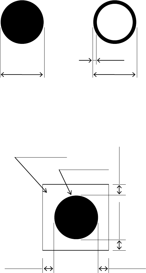
- The standard marks represent the thirteen (13) forms as shown in the following block,
“Forms of Recognition Marks.”
- For any mark other than those shown in the said block, customers shall make templates
to allow for recognition through a pattern matching.
Note 1: Up to three PWB reference marks and up to six component placement area
positioning marks are supported.
Note 2: Within a field of vision, there should be no similar form pattern other than the
subjected form patterns.
- For regular triangles, checker patterns and users’ templates, the 90°up-side-down
marks can also be recognized.
Circle
Square
Diamond
Regular
triangle
Up-side-down
triangle
Checker
pattern
Cross
Inside-blank
circle
Inside-blank
square
Inside-blank
diamond
Inside-blank
up-side-down
triangle
Checker
pattern
Inside-blank
Regular
triangle
Figure 8 Forms of Recognition Marks
The recognition marks shall all comply with EIAJ ET-7302 “Recognition marks for on-surface
placed PWBs.”
Component placement
area positioning marks
Component positioning
marks
Placement group
PWB reference marks
- 21 -
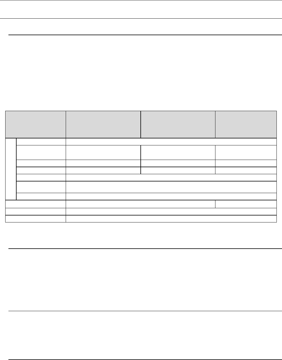
Dimensions and tolerances
The outside dimensions shall range from 0.5 mm up to 3.0mm, whose tolerance, less than
10%.
For all the inside-blank forms, the edging line width shall be more than 0.2 mm.
Figure 9
Dimensions and tolerances of recognition marks.
It is desirable that there is, around each recognition mark, a space having nothing of such
other marks as conductor pattern, solder resist, marking and the like, and that this space
dimensions is a larger square than the mark by 0.5 mm or more from the outer
circumference of the recognition marks.
Figure 10
Clearances of recognition marks
0.5
to 3.0mm
0.5 to 3.0mm
0.2 mm or more
Clearance area
Recognition mark
0.5 mm or more
0.5 mm or more
0.5 mm or more
0.5 mm or more
- 22 -
5.
Standard Functions And Optional Functions
5.1. Standard
5.1.1. Component database function
The component database is software intended for the creation and management of
“Component data”, which is used in the production program, with a mounter and/or an
external programming unit (EPU),
Using component database can shorten the creation time of production program and edit the
data by managing component data collectively.
* External PC is necessary to use component database.
Specification that the PC for component database requires is shown below.
Item
Recommended
specification
Windows XP Professional
Edition SP2 or later
Recommended
specification
Windows Vista Business
Edition SP1 or later
Recommended
specification
Windows 10
Professional (64bit)
Operable PC
Main unit
Compatible with IBM PC-AT
CPU
Pentium
Ⅳ
3.2GHz or more
Intel Core2 Duo
2.40GHz or more
Intel Core i3
3.0GHz or more
Memory
1GB or more
2GB or more
8GB or more
Hard disc
10GB or more
40GB or more
50GB or more
CD-ROM drive
1 unit or more
Mouse To be supported with OS
Bus slot
Slot for network x 1
Image resolution
1024
×
768
1366×768
Printer
To be supported with OS
Interface
LAN connector x 1 accommodating 100BASE-TX/10BASE-T
*1 This function is not supported with Windows 7.
5.1.2. Height Measurement System (HMS)
When preparing the pick-up data, the component pick-up position and height shall all be
measured via the laser sensors. Components (for example, LEDs) whose pick-up surface is
transparent such as glass and a substance in a mirror state from which the light is fully
reflected, blue components and 0603 or smaller components are all be excluded from the
subjects of the HMS. The HMS is used to set a teaching spot also.
5.1.3. Feeder Float Detecting Sensor
This function is provided to prevent mechanical troubles caused by improper installation of
tape or stick feeders. When this sensor detects an improperly-installed feeder, it stops the
X-Y axes, and warns an operator.
5.1.4. Vacuum pump
This pump allows the machine to reduce air consumption of the compressor, and improve
the stability of air supply when it picks up a component.