3OM-1208-011_w.pdf - 第130页
3-43 AIVEDT -ID (D02_07) H [mm] The component placement height can be corrected. H Component PCB Reference Plane Fig. 3C32 Note When a parameter is set as "H" data in the last line (last step No.), it becomes i…
3-42
AIVEDT-ID
(D02_06)
Z=theta [deg]
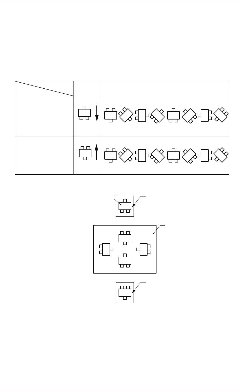
Set angles for component placement.
The placement angles must be determined according to the packaged
posture of components on the tape feeder.
Example:
0� 45� 90� 135� 180� 225� 270� 315�
Front Side of Machine
Z=Theta
(Angle)
Feeder Bases #1
and #3
Packaged
Posture
User Direction
of T
ape Feed
Packaged
Posture
User Direction
of T
ape Feed
Feeder Bases #2
and #4
Rear Side of Machine
Packaged Posture of
Component on Feeder
Tape Feeder
PCB
Tape Feeder
0�
90�
180�
270�
Fig. 3C31
0606-009
1.5 Placement Data
3-43
AIVEDT-ID
(D02_07)
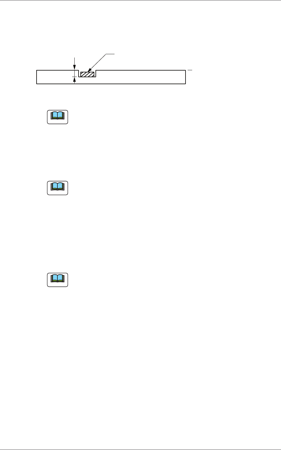
H [mm]
The component placement height can be corrected.
H
Component
PCB
Reference Plane
Fig. 3C32
Note
When a parameter is set as "H" data in the last line (last step No.), it
becomes invalid because "E" is set in the "C (Control Command)" text
box.
(D02_08)
Fdr No.
Set the Nos. of the feeders loaded with components.
Note
The feeder Nos. (Fdr Nos.) to be set here must be specified in the
placement feeder location data.
(D02_09)
V
Select one of the following options for the local recognition mode.
00 :
The local recognition is not performed.
01 :
The local recognition (1-point recognition) is performed.
02
:
The local recognition (2-point recognition) is performed.
Note
(a) The above-described option must be selected after "Enable" is set in
the "local" text box of the label "PEC recognition Mode" in the "PEC
Recognition Data" tab sheet ("A02_03" in Operation Data).
(b) Refer to "(D02_12), (D02_13), and (D02_14)" for how to specify the
coordinates and mark codes for "Local Recognition".
0606-009
1.5 Placement Data
3-44
AIVEDT-ID
(D02_10)
C
Enter some of the following control commands.
Notice
If a control command other than the following ones is used, the step
becomes invalid.
- (hyphen) :
This command handles the steps as those for component
placement.
S :
This command invalidates the steps specified as those for
component placement.
C :
This command invalidates the steps specified as those for
component placement.
Note:
As for dispensers, these steps become valid.
D :
This command handles the steps as those for component
placement.
Note:
As for dispensers, these steps become invalid.
E :
This shows the end of the placement data (O).
When placement data (O) is not created, this shows the
end of the steps in the placement data (P).
P, Q :
This shows the end of the placement data (P) of a
repetitive pattern program.
B :
When the unit PCB BBR function (option) is used, set
this control command for P-No. 1.
See Note (b).
0, 1, 2, 3, 4, 5, 6, 7, 8, 9:
These control commands are used to enable the block
sorting function.
See Note (a).
Note
(a) When the block sorting function is used in the following case, the
productivity will be improved because components are placed on the
specified areas of unit PCBs.
•
It is required to change the nozzles in the nozzle stocker for
component placement on a certain unit PCB according to the
repetitive pattern program.
(b)
Do not set the B command in any lines except "P-No. 1".
(c) Confirm that "0" (zero) is set in the "X [mm]", "Y [mm]", "Z=theta
[deg]", "H", and "Fdr No." text boxes of the last line (last step No.)
and set "E", "P", or "Q".
0606-009
1.5 Placement Data