3OM-1208-011_w.pdf - 第314页
6-81 AIVEDT -ID V -groove Size [mm] When the V -grooved nozzle is used for cylindrical components, set the size of the V -groove in the corresponding text box. Fig. 3F73 Note In the case of the nozzle without a V groove,…
6-80
AIVEDT-ID
Nozzle Recog
1.0 mm
2.0 mm
Length
Diffusion
Plate
Reference Plane for
Nozzle Attachment
Height for
Recognition
Fig. 3F71
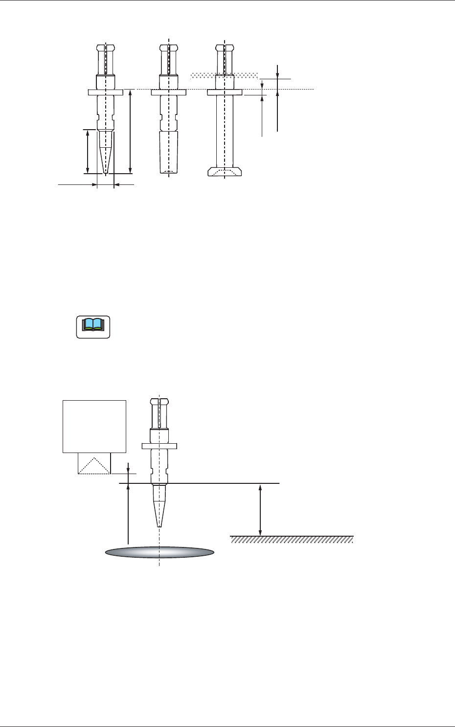
Lighting Method
Select one of the following options as a lighting method for the nozzle
recognition plane.
Back ltg, Fr ltg #1 (Ring Dn), Fr ltg #2 (Coax),
Fr ltg #3 (Ring Up)
Note
The following condition is required for recognition of a nozzle.
•
The nozzle height direction should be the one as depicted in the figure
below.
•
The object nozzle for recognition should be arranged in the camera
sensor.
10.0 mm
PCB Surface
Linear
Measure
Sensor Light
Emitter
Component Recognition Camera Focus Position
1.0 mm or more
Camera Center
Fig. 3F72
Level [mm]
Set the height (level) of the nozzle recognition plane in comparison with the
nozzle end.
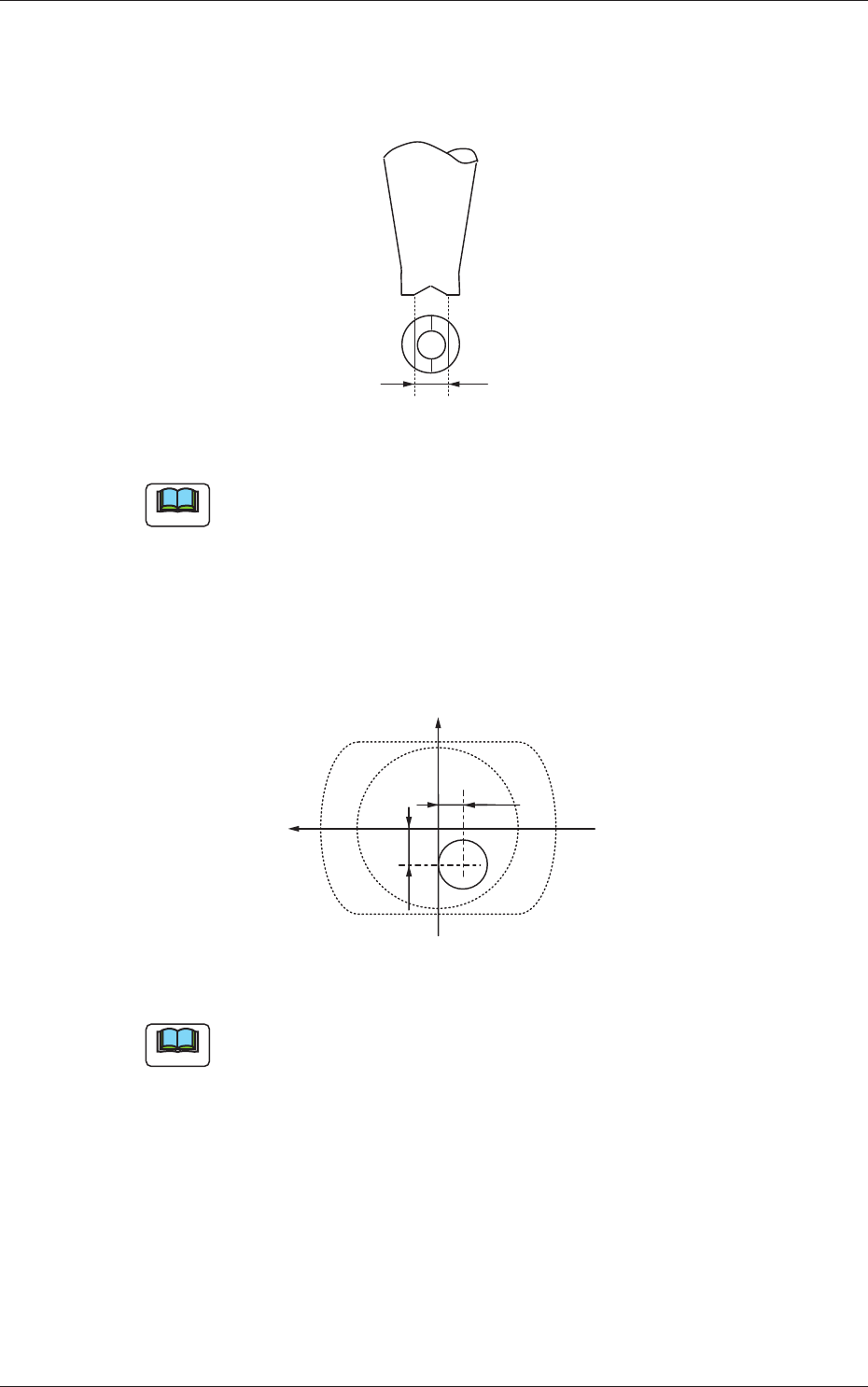
Outer Size [mm]
Set the outer diameter of the nozzle recognition plane.
0606-009
3.2 Nozzle Data
6-81
AIVEDT-ID
V-groove Size [mm]
When the V-grooved nozzle is used for cylindrical components, set the
size of the V-groove in the corresponding text box.
Fig. 3F73
Note
In the case of the nozzle without a V groove, set "0.00" in the
corresponding text box.
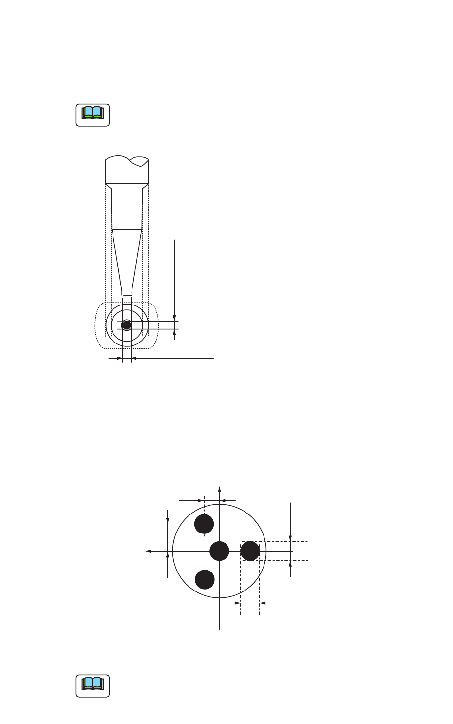
Eccntrc X (Horizontal), Y (Vertical) [mm]
When the center of the nozzle end is eccentric in comparison with the
outer shape of the nozzle, set the eccentricity in both X and Y directions
in the coordinate system viewed from the nozzle top side (clamp side).
-Y1
+X
+Y
-X1
Fig. 3F74
Note
Set "0.00" in both text boxes for standard nozzles.
0606-009
3.2 Nozzle Data
6-82
AIVEDT-ID
Pu Holes 1 through 4
Size X [mm], Y [mm]
Set the dimensions of the nozzle pickup holes in the text boxes.
Up to 4 pieces of pickup holes can be specifi
ed.
Note
In the case of "Circle", set the same dimensions for "Size X [mm]" and
"Size Y [mm]"
In the case of "Rect", set Dimensions X and Y.
Outside Dimension X
Set the dimensions of the pickup hole.
Outside Dimension Y
Fig. 3F75
Lct X [mm], Y [mm]
Set parameters representing the locations of the pickup holes based on
the center of the nozzle ends.
Up to 4 pieces of pickup holes can be specifi
ed.
+X
Size Y1
Size X1
+X2
+Y2
+Y
Fig. 3F76
Note
When no relevant hole is found, set "+0.00" in both text boxes.
0606-009
3.2 Nozzle Data