3OM-1208-011_w.pdf - 第248页
6-15 AIVEDT -ID [1] X (Horizontal) and Y (V ertical) [mm] These of fset parameters are used to adjust th e positional deviation based on the design dimensions representing the component pickup position for each individua…

6-14
AIVEDT-ID
Feeder offset parameters are added to actual offset values.
Actual Offset Values = Feeder (A) Offset + Feeder (B) Offset
Note
Perform the same operations for the feeders (Feeder Base #1: 101 to 150,
#2: 201 to 250, #3: 301 to 350, and #4: 401 to 450) on each feeder base at
the "Feeder Base #1" through "Feeder Base #4" tab sheets.
Offset Parameters
Set the following offset values for each individual feeders (Feeder Base
#1: 101 to 150, #2: 201 to 250, #3: 301 to 350, and #4: 401 to 450).
2.1 Device Offset Data
0606-009
6-15
AIVEDT-ID
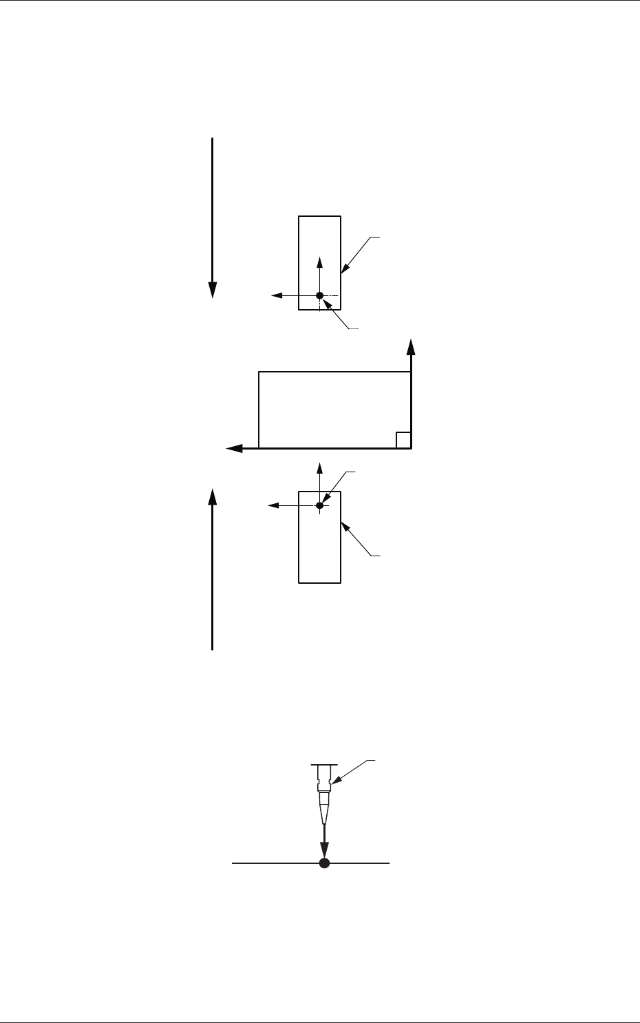
[1] X (Horizontal) and Y (Vertical) [mm]
These offset parameters are used to adjust the positional deviation based
on the design dimensions representing the component pickup position
for each individual feeder slot Nos. (Fdr Nos.).
F211
F111
Rear Feeder
Front Feeder
Front Side of Machine
Y (+)
X (+)
Pickup Position
Pickup Position
Direction of Tape FeedDirection of Tape Feed
Fig. 3F13
[2] L (Height) [mm]
Nozzle
L (+)
Pickup Reference Level
Fig. 3F14
When a value is entered with a plus (+) sign, the pickup height is reflected on
the direction in which the descending stroke of the nozzle will increase.
2.1 Device Offset Data
0606-009
6-16
AIVEDT-ID
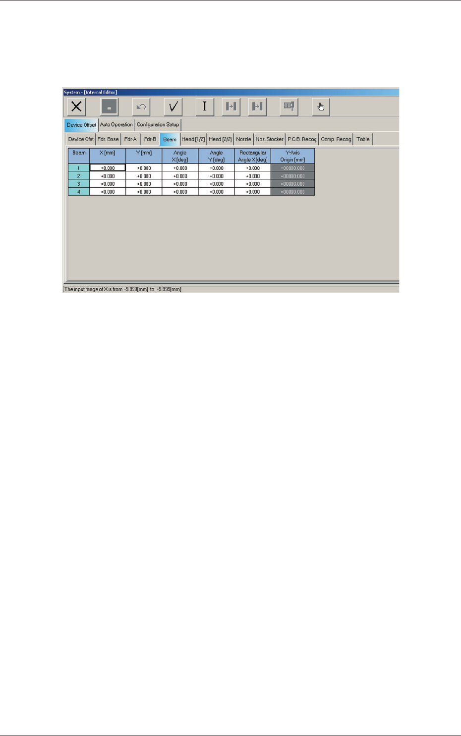
2.1.4 Beam Offset
When the "Beam" tab is pressed in the "Device Offset" tab sheet, the
following tab sheet appears.
Fig. 3F15 "Beam" Tab Sheet
2.1 Device Offset Data
0606-009