3OM-1208-011_w.pdf - 第256页
6-23 AIVEDT -ID 2.1.8 Head Rotational Center Offset When the "Head [1/2]" tab is pressed in the "Device Offset" tab sheet and the "Hd Center" tab is selected, the following tab sheet appears…
6-22
AIVEDT-ID
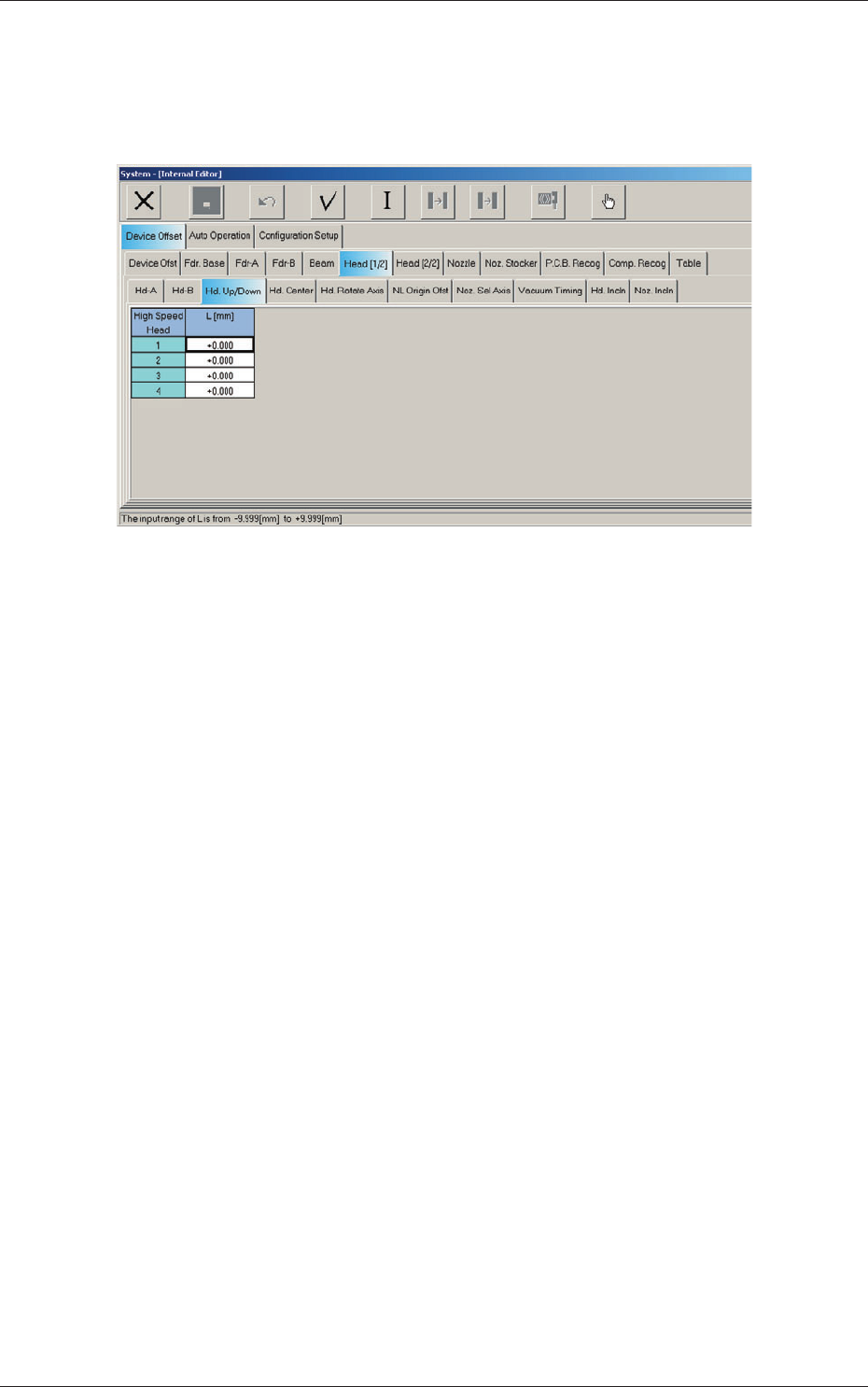
2.1.7 Head Up/Down Offset
When the "Head [1/2]" tab is pressed in the "Device Offset" tab sheet and the
"Hd Up/Down" tab is selected, the following tab sheet appears.
Fig. 3F21 "Head Up/Down" Tab Sheet
Head 1, Head 2, Head 3, and Head 4
L (Height) [mm]
The set parameters are used to adjust the deviations (caused when the
master nozzle is attached to the head and lowered by the specified
d
ist
ance with the combined operations of the head and nozzle U/D axes)
based on the design value of the distance between the upper surface of
PCB and the lower surface of the nozzle. The amount of movement of
each axis is separately reviewed.
When the measured value is greater than the design one, a plus sign
must be affixed to the offset data.
0606-009
2.1 Device Offset Data
6-23
AIVEDT-ID
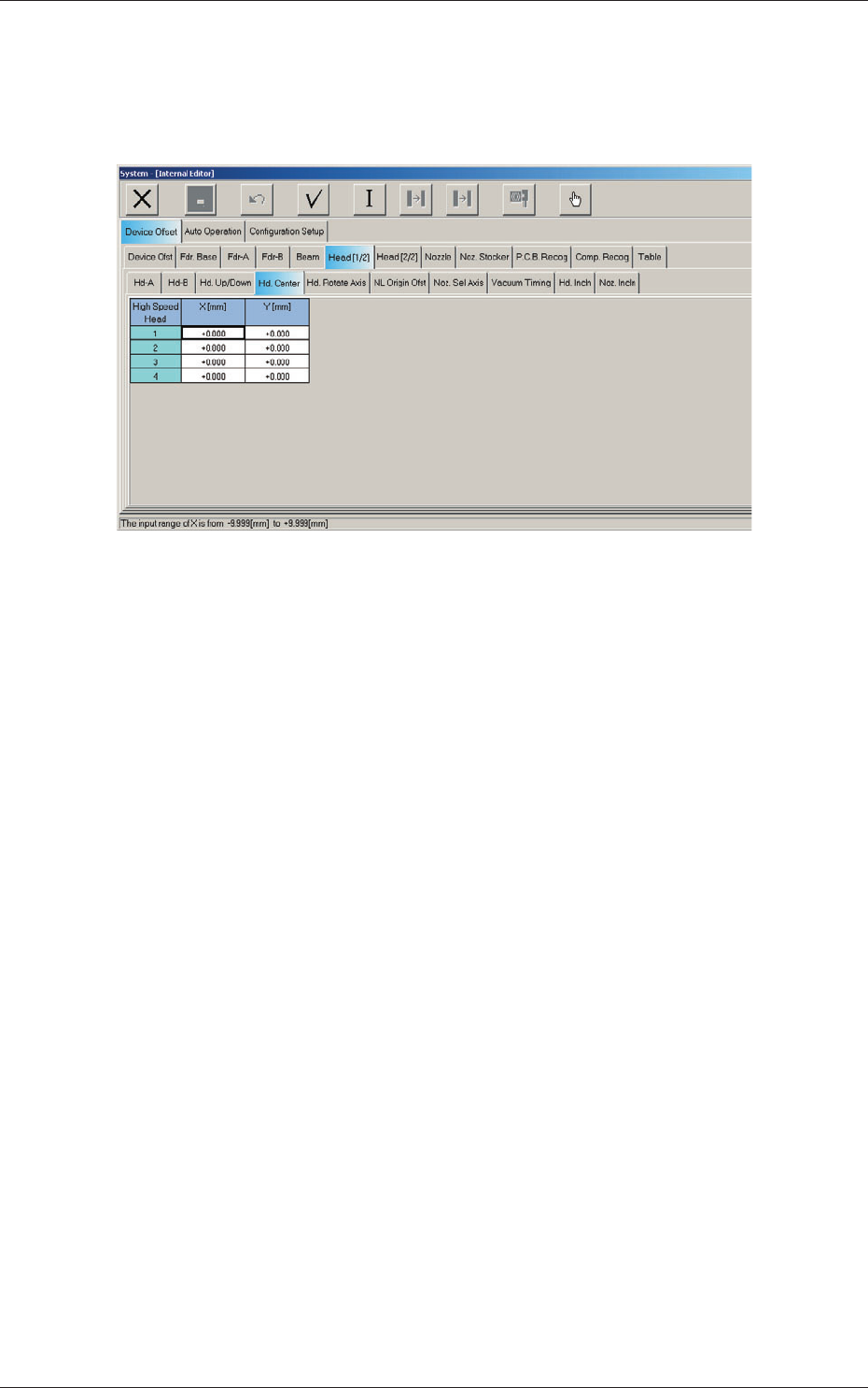
2.1.8 Head Rotational Center Offset
When the "Head [1/2]" tab is pressed in the "Device Offset" tab sheet and the
"Hd Center" tab is selected, the following tab sheet appears.
Fig. 3F22 "Head Center" Tab Sheet
0606-009
2.1 Device Offset Data
6-24
AIVEDT-ID
Head 1, Head 2, Head 3, and Head 4
X (Horizontal), Y (Vertical) [mm]
The set parameters are used to adjust the deviations in the design value
betwe
en the head rotational center and the center of the PEC recognition
camera.
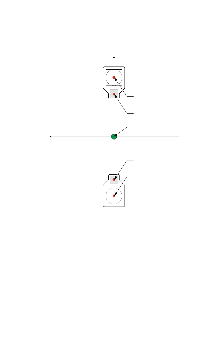
Xm (+)
Ym (+)
Xm-Ym : Machine Reference
Coordinate System
Center of PEC Recognition Camera
Center of PEC Recognition Camera
Head Rotational Center
Head Rotational Center
Pm. Machine Reference
Coordinate Origin
Fig. 3F23
0606-009
2.1 Device Offset Data