3OM-1208-011_w.pdf - 第166页
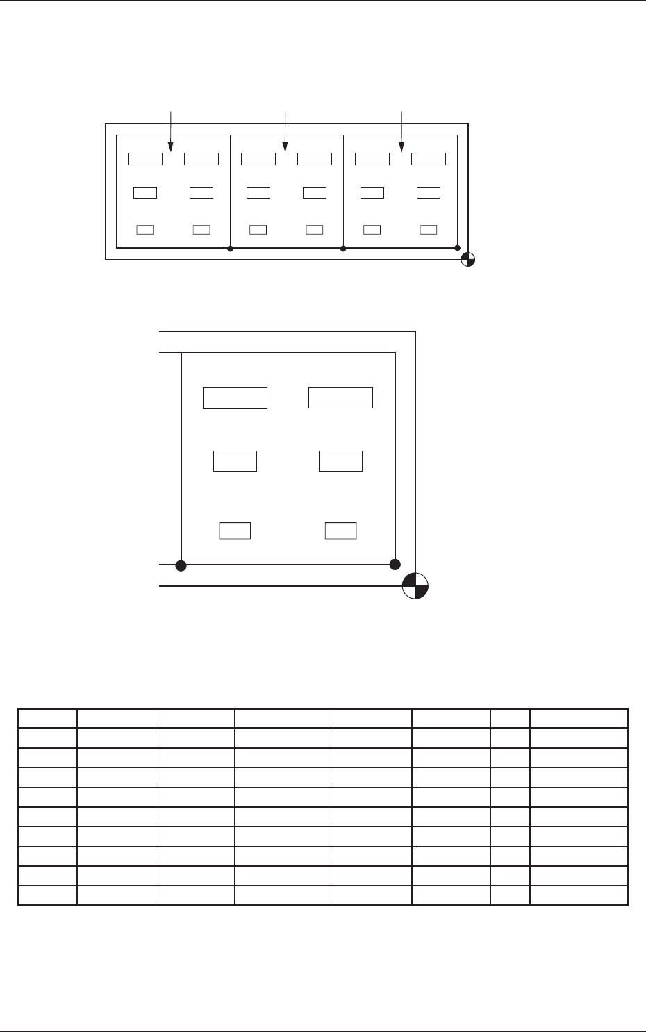
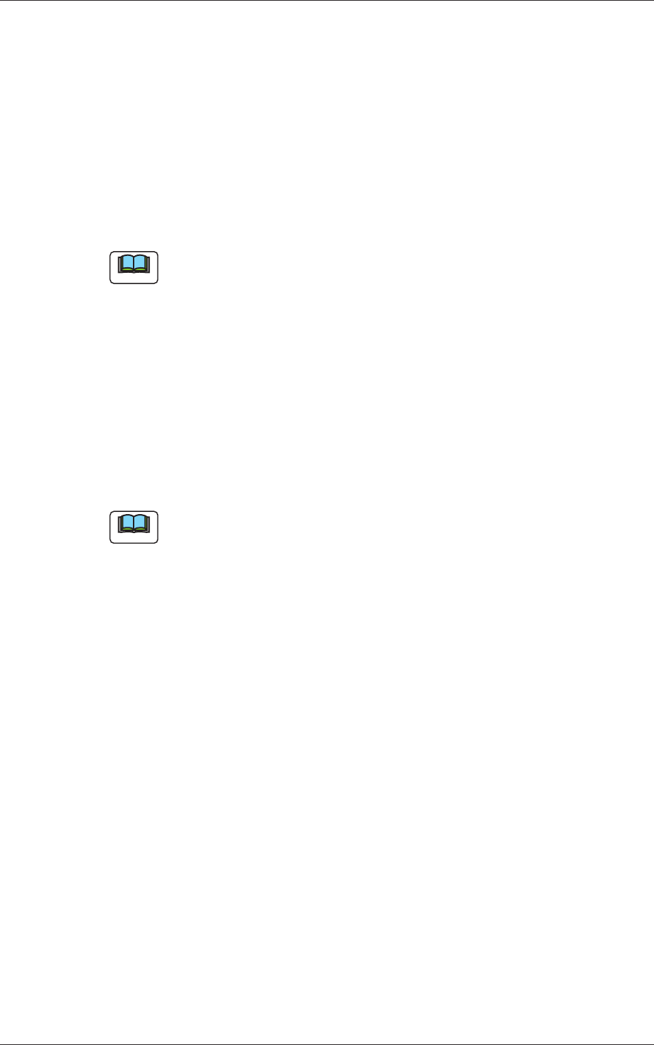
3-79 AIVEDT -ID (1) Information on Pattern Program Creation • Example of Patterns Placement Coordinate Reference Pattern 3 Pattern 2 Pattern 1 Fig. 3C58 Whole View C6 (X 6 ,Y 6 ) (X 4 ,Y 4 ) (X 2 ,Y 2 ) (X 1 ,Y 1 ) (X 3 …

3-78
AIVEDT-ID
3.5 Placement Data for Block Sorting Function
Placement steps are grouped into some blocks and component placement
sequence can be specified for each block.
The following describes the method of block sorting according to the outside
diameters of the nozzles.
•
Outside Diameters of Nozzles
After the nozzle IDs in the placement feeder location data are confirmed,
the outside diameters are examined, using the nozzle type data of the
placement head/nozzle data.
•
Nozzle Type Data
Press the [MACH SET] button on the main menu bar of the "SYSTEM >>
DISPLA
Y SETTING" window and select the [NOZ. DATA] button on the
submenu bar.
Press the "Nozzle Data" tab in the "Nozzle Data" window.
Follow the same procedure as described in "3.2 Repetitive Patterns (Image
Recognition Enabled)" to create the data, except for the placement data
(P-data).
0606-009
3.5 Placement Data for Block Sorting Function
3-79
AIVEDT-ID
(1) Information on Pattern Program Creation
•
Example of Patterns
Placement
Coordinate
Reference
Pattern 3 Pattern 2 Pattern 1
Fig. 3C58 Whole View
C6
(X
6,Y6)
(X
4,Y4)
(X
2,Y2)
(X
1,Y1)
(X
3,Y3)
(X
5,Y5)
C4
C2
C3
C1
C5
Placement
Coordinate
Reference
Fig. 3C59 Pattern 1 (Magnified View)
(2) Creation of P-Data
Table 3C22
P-No. X [mm] Y [mm] Z = theta [deg] H [mm] Fdr No. C Comment
1 X
1
Y
1
Z
1
+0.000 XXX - C1
2 X
2
Y
2
Z
2
+0.000 XXX - C2
3 +000.000 +000.000 +000.00 +0.000 000 1
4 X
3
Y
3
Z
3
+0.000 XXX - C3
5 X
4
Y
4
Z
4
+0.000 XXX - C4
6 +000.000 +000.000 +000.00 +0.000 000 2
7 X
5
Y
5
Z
5
+0.000 XXX - C5
8 X
6
Y
6
Z
6
+0.000 XXX - C6
9 +000.000 +000.000 +000.00 +0.000 000 P
0606-009
3.5 Placement Data for Block Sorting Function
3-80
AIVEDT-ID
•
Example of Block Sorting
(1) Classify the components that require the same outside diameters of the
nozzles into one.
Set the grouped components that require the smallest outside diameter
(nozzle) in the smallest P-No. step.
In the above example, C1 and C2 are set in P-Nos. 1 and 2.
(2) Set "1" in the "C" text box of P-No. 3 and "0" (zero) in the other text
boxes of the step line.
This step is regarded as a delimit of one group.
Note
(a) No components are placed for the delimit step.
(b) Any number (0 to 9) can be used as a control command.
"1" is used in the above example.
(3) Keep the same procedure to make each step as follows.
•
Set "C3" and "C4" in the "Comment" text boxes of P-Nos. 4 and 5.
•
Set "2" in the "C" text box of P-No. 6 and "0" (zero) in the other
text boxes of the step line.
•
Set "C5" and "C6" in the "Comment" text boxes of P-Nos. 7 and 8.
(4) Create the last step in the same way as a normal program. Be sure to set
"P" as a control command in the "C" text box.
Note
Up to 20 groups can be created in one pattern program.
0606-009
3.5 Placement Data for Block Sorting Function