3OM-1208-011_w.pdf - 第252页
6-19 AIVEDT -ID [4] Y -Axis Origin [mm] The set parameters are used to maintain the beam condition (position) set up right after the machine was assembled. Use the values fed back automatically from the motion controller…
6-18
AIVEDT-ID
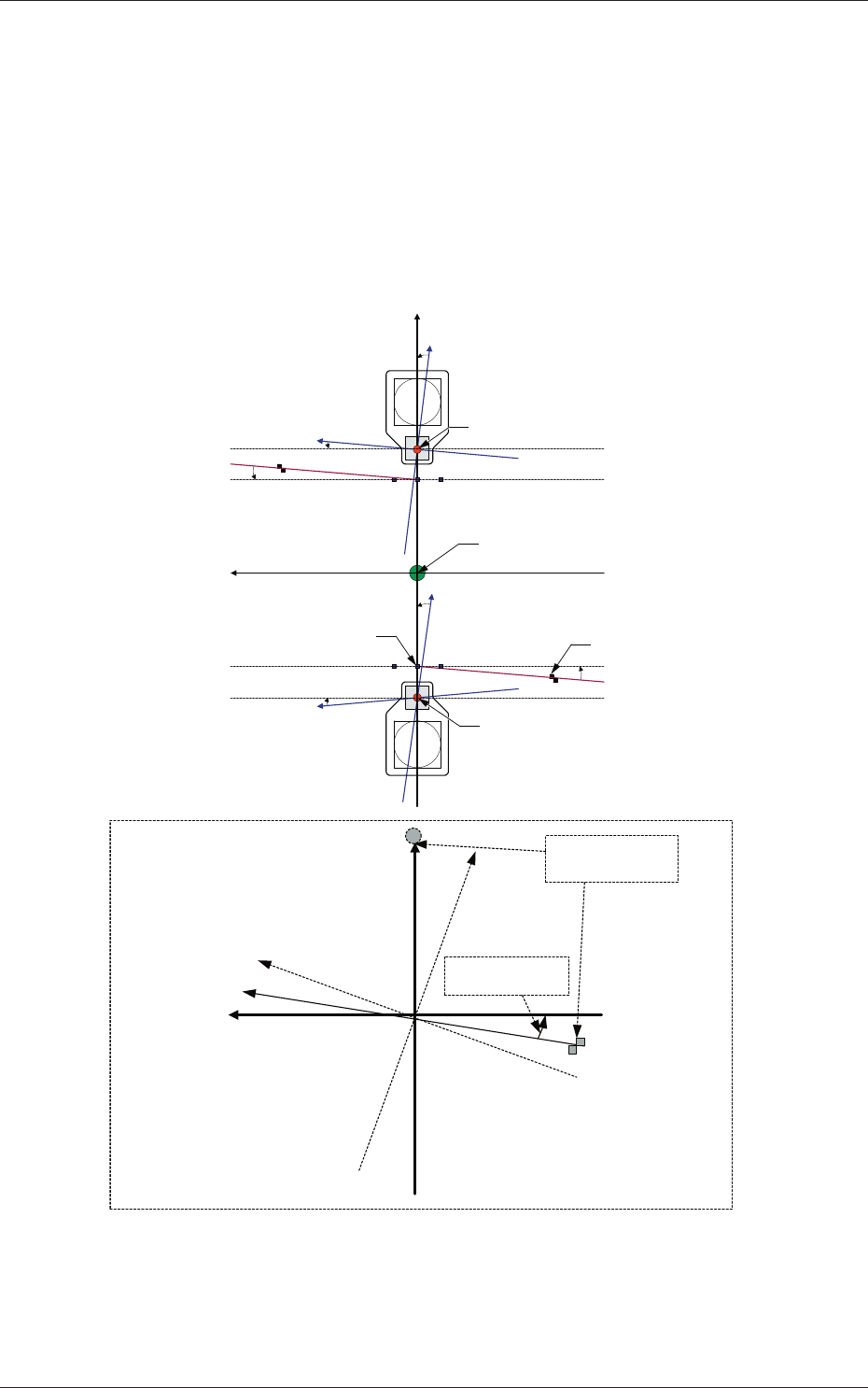
[3] Rectangular Angle X [deg]
These parameters represent the amount of angular deviations (X
directions) of the mark on the machine in comparison with the X
directions in the machine reference coordinate system.
The set parameters are used to check the three marks on the area of the
machine where only a little positional change can be made according to
temperature changes and adjust the beam X/Y axes such that they can
cross at right angles.
Xm (+)
Ym (+)
Yb (+)
Xb (+)
Yb (+)
Xb (+)
Xm'
Machine Reference
Coordinate System
Mark Coordinate
System
Beam Coordinate
System
Mark on Machine
Rectangular Angle
X [deg]
Head Origin
Head Origin
Pm. Machine Reference
Coordinate Origin
Standard Mark 2
Xm-Ym : Machine Reference
Coordinate System
Xb-Yb : Real Beam Coordinate
System
Standard Mark 1
Fig. 3F17
2.1 Device Offset Data
0606-009
6-19
AIVEDT-ID
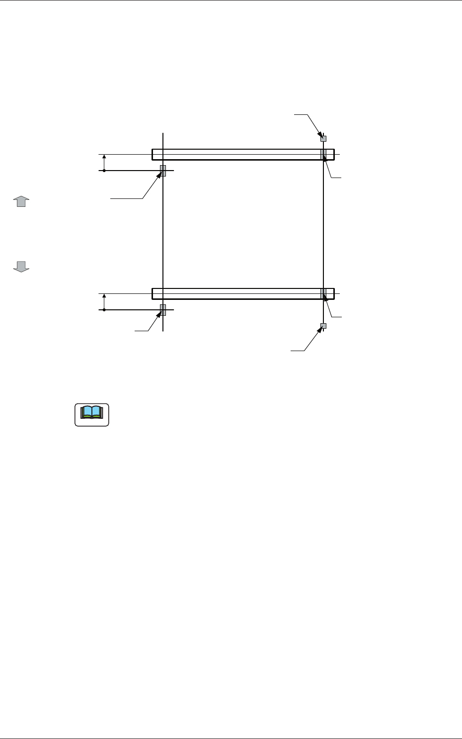
[4] Y-Axis Origin [mm]
The set parameters are used to maintain the beam condition (position)
set up right after the machine was assembled.
Use the values fed back automatically from the motion controller after
the Y-axis is zeroed (adjustment mode).
Master Side
Slave Side
Beam
Beam
Zeroing
Direction
Zeroing
Direction
Y-Axis Origin Offset
= (+) Value
Origin Mark
(Origin Signal Position)
Origin Mark
(Origin Signal Position)
Origin Mark
(Origin Signal Position)
Origin Mark
(Origin Signal Position)
Limit Sensor
Limit Sensor
Y-Axis Origin Offset
= (+) Value
Fig. 3F18
Note
(a) The displayed parameters cannot be edited manually.
(b) The Y-axis origin offset indicates where the origin signal position of
the master axis is located when viewed in the zeroing direction from
the origin signal position of the slave axis.
A plus sign will be affixed when the origin signal position is located
in the same direction as the zeroing one. When it is located in the
opposite direction, a minus sign is affixed.
2.1 Device Offset Data
0606-009
6-20
AIVEDT-ID
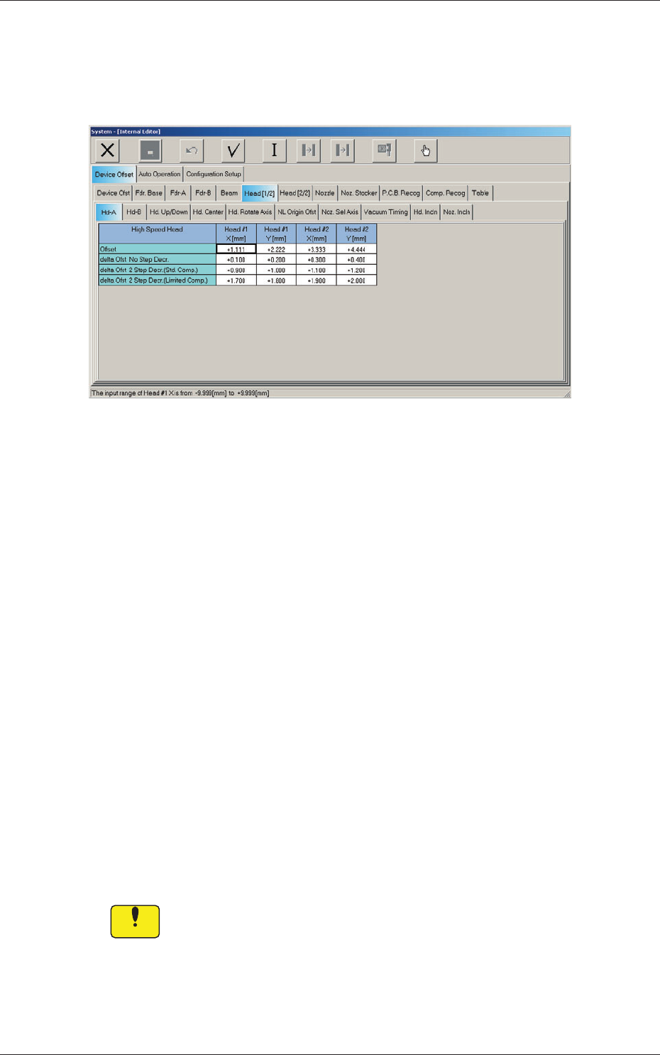
2.1.5 Head (A) Offset
When the "Head [1/2]" tab is pressed in the "Device Offset" tab sheet and the
"Hd-A" tab is selected, the following tab sheet appears.
Fig. 3F16 "Head-A" Tab Sheet
Head 1, Head 2, Head 3, Head 4
X, Y [mm]
[1] Offset
The set parameters are used to adjust the deviations of the head
rotational centers caused due to the movement of the head U/D axes.
[2]
delta Ofst No. Step Decr.
When no speed deceleration for component placement is specified in
the library data and the position for the placement is calculated, the
proper deceleration rate is converted and added.
[3]
delta Ofst 2 Step Decr. (Std. Comp.)
When a standard component is selected in the library data and the
position for the placement is calculated, the proper deceleration rate is
converted and added.
[4]
delta Ofst 2 Step Decr. (Limited Comp.)
When a limited (special) component is selected in the library data and
the position for the placement is calculated, the proper deceleration rate
is converted and added.
Notice
Do not change the parameters unless necessary. They are factory-specified
upon shipment of the machine.
2.1 Device Offset Data
0606-009