3OM-1208-011_w.pdf - 第249页
6-16 AIVEDT -ID 2.1.4 Beam Offset When the "Beam" tab is pressed in the "Device Offset" tab sheet, the following tab sheet appears. Fig. 3F15 "Beam" T ab Sheet 2.1 Device Offset Data 0606-00…
6-15
AIVEDT-ID
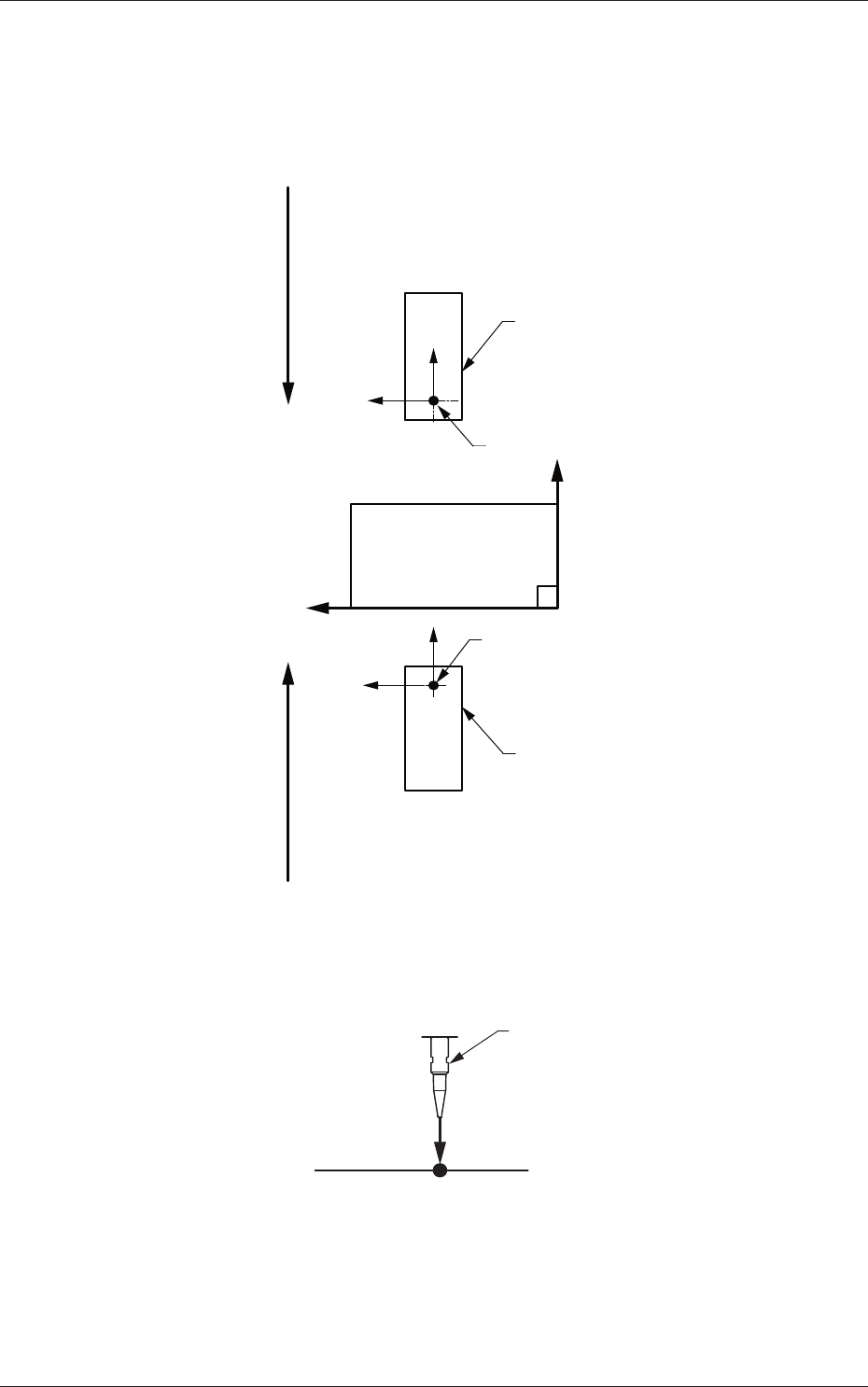
[1] X (Horizontal) and Y (Vertical) [mm]
These offset parameters are used to adjust the positional deviation based
on the design dimensions representing the component pickup position
for each individual feeder slot Nos. (Fdr Nos.).
F211
F111
Rear Feeder
Front Feeder
Front Side of Machine
Y (+)
X (+)
Pickup Position
Pickup Position
Direction of Tape FeedDirection of Tape Feed
Fig. 3F13
[2] L (Height) [mm]
Nozzle
L (+)
Pickup Reference Level
Fig. 3F14
When a value is entered with a plus (+) sign, the pickup height is reflected on
the direction in which the descending stroke of the nozzle will increase.
2.1 Device Offset Data
0606-009
6-16
AIVEDT-ID
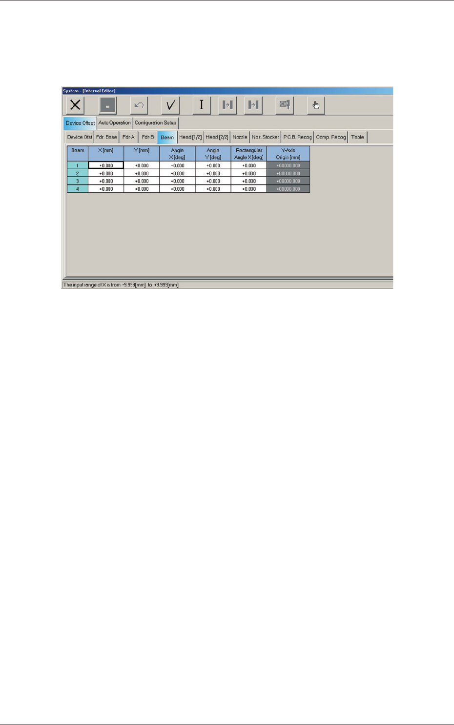
2.1.4 Beam Offset
When the "Beam" tab is pressed in the "Device Offset" tab sheet, the
following tab sheet appears.
Fig. 3F15 "Beam" Tab Sheet
2.1 Device Offset Data
0606-009
6-17
AIVEDT-ID
[1] X (Horizontal) and Y (Vertical) [mm]
The set parameters are used to adjust the positional deviation based on
the design dimensions representing the distance between the machine
reference coordinate origin and the center of the PEC recognition
camera at the head origin.
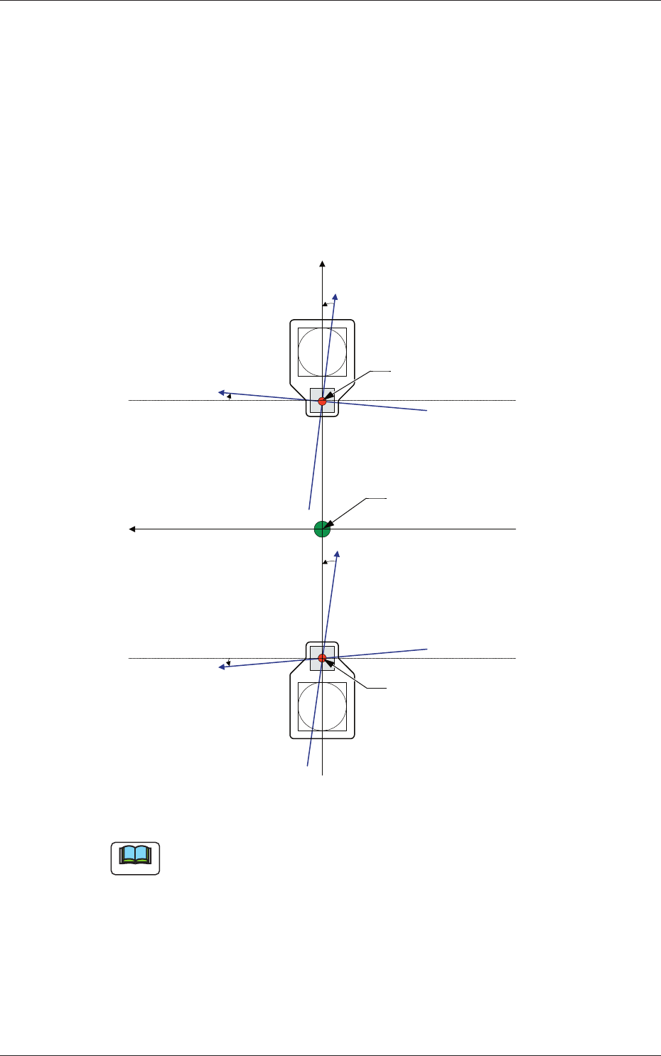
[2] Angle X and Angle Y [deg]
The set parameters are used to adjust the beam X and Y axes to the
machine reference coordinate system.
Xm (+)
Ym (+)
Yb (+)
Xb (+)
Yb (+)
Xb (+)
Xm-Ym : Machine Reference
Coordinate System
Xb-Yb : Real Beam Coordinate
System
Head Origin
Head Origin
Pm. Machine Reference
Coordinate Origin
Fig. 3F16
Note
A plus values must be entered in the "Angle X [deg]" and "Angle Y [deg]"
text boxes when the real beam coordinate system is tilted counterclockwise
(based on the machine reference coordinate system).
2.1 Device Offset Data
0606-009