3OM-1208-011_w.pdf - 第267页
6-34 AIVEDT -ID 2.1.15 Head Rotation Correction Offset When the "Head [2/2]" tab is pressed in the "Device Offset" tab sheet and the "Hd. Rotate Corr . Head #1" tab is selected, the followin…
6-33
AIVEDT-ID
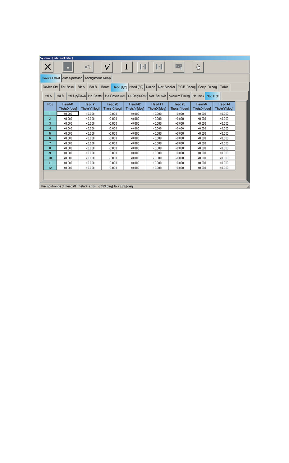
2.1.14 Nozzle Inclination Offset
When the "Head [1/2]" tab is pressed in the "Device Offset" tab sheet and the
"Noz. Incln" tab is selected, the following tab sheet appears.
Fig. 3F31 "Noz. Incln" Tab Sheet
Nozzles 1 through 12
Head #1, Head #2, Head #3, and Head #4
Theta X [deg], Theta Y [deg]
Th
ese offsets are used to correct the deviations in the X and Y directions
that will be caused due to the inclination of the nozzle shaft while the
NL-axis is moving down.
2.1 Device Offset Data
0606-009
6-34
AIVEDT-ID
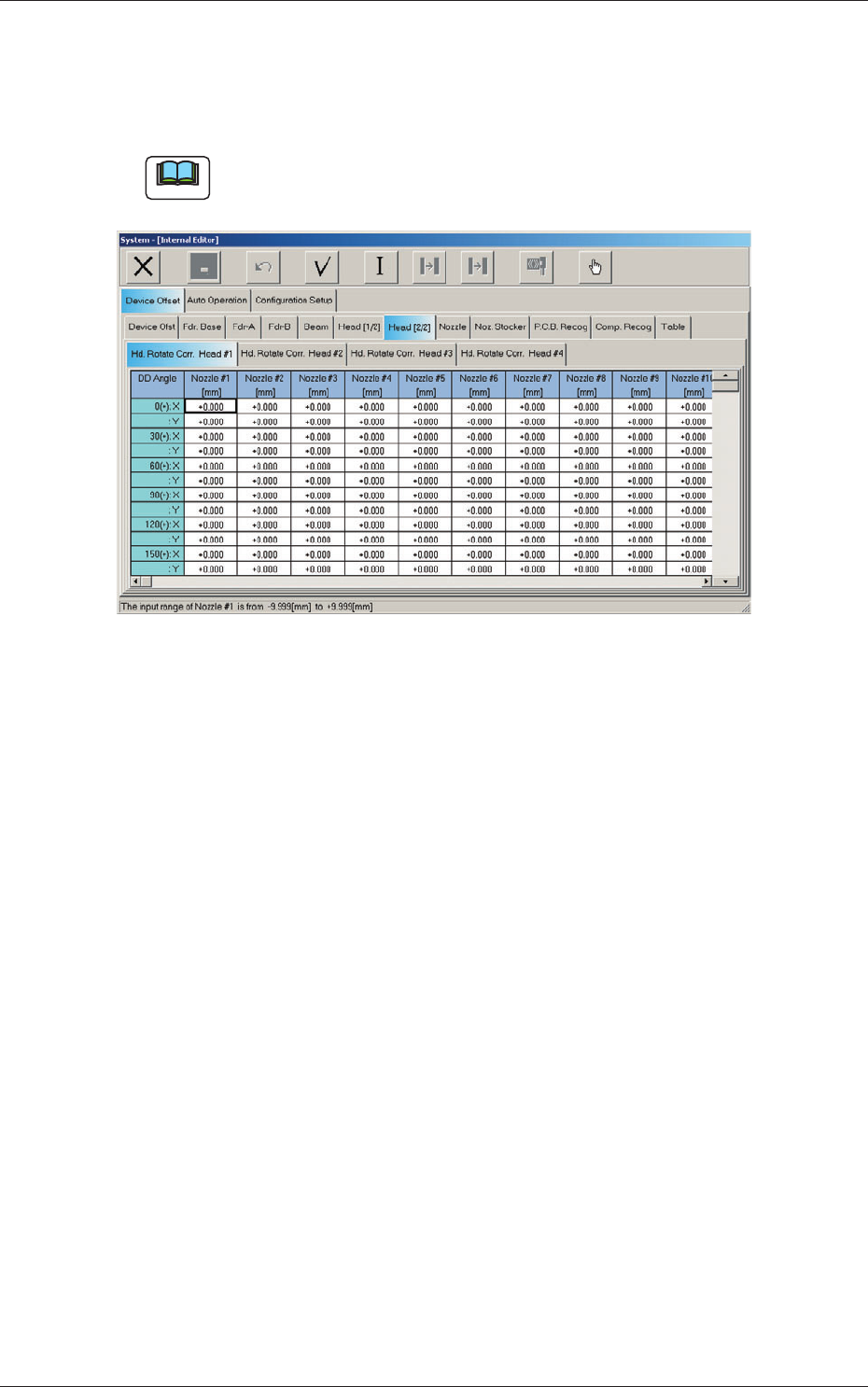
2.1.15 Head Rotation Correction Offset
When the "Head [2/2]" tab is pressed in the "Device Offset" tab sheet and the
"Hd. Rotate Corr. Head #1" tab is selected, the following tab sheet appears.
Note
A similar tab sheet will appear with the [Hd. Rotate Corr. Head #2], the
[Hd. Rotate Corr. Head #3], or the [Hd. Rotate Corr. Head #4] tab.
Fig. 3F32 "Hd. Rotate Corr. Head #1" Tab Sheet
Nozzles #1 through #12
DD An
gles 0 (+) to 330 (+) and 0 (-) to 330 (-), X [mm], Y [mm]
(Not
Available)
2.1 Device Offset Data
0606-009
6-35
AIVEDT-ID
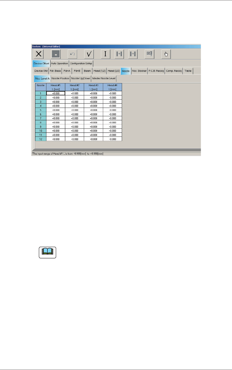
2.1.16 Nozzle Level A Offset
When the "Nozzle" tab is pressed in the "Device Offset" tab sheet and the
"Noz. Level A" tab is selected, the following tab sheet appears.
Fig. 3F33 "Noz. Level A" Tab Sheet
Nozzle 1 through 12
Head #1, Head #2, Head #3, and Head #4
L (Height) [mm]
Each parameter indicates the offset of the bottom level of the normal
nozzles on each individual heads.
Measure each nozzle bottom level with a linear measure while the
nozzle U/D axis is zeroed and save the difference between the level and
the master nozzle level offset.
Note
These parameters are calculated using the formula "Nozzle Level Offset =
Master Nozzle Level - Measured Value of Normal Nozzle Level".
2.1 Device Offset Data
0606-009