3OM-1208-011_w.pdf - 第261页
6-28 AIVEDT -ID 2.1.1 1 Nozzle Selection Axis Offset When the "Head [1/2]" tab is pressed in the "Device Offset" tab sheet and the "Noz. Sel Axis" tab is selected, the following tab sheet ap…
6-27
AIVEDT-ID
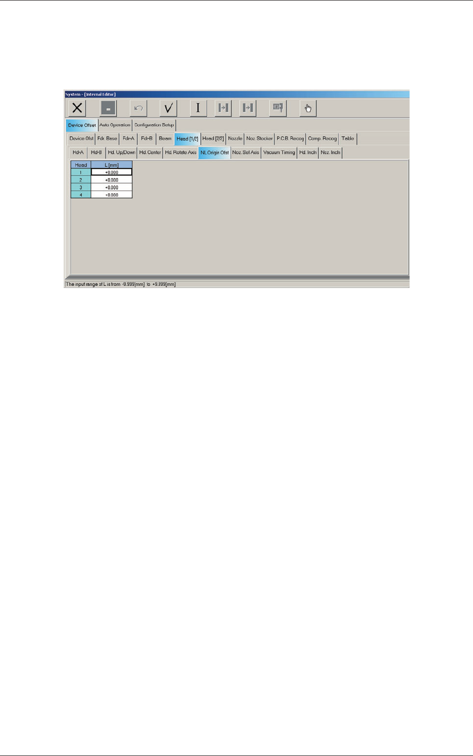
2.1.10 NL Origin Offset
When the "Head [1/2]" tab is pressed in the "Device Offset" tab sheet and the
"NL Origin Ofst" tab is selected, the following tab sheet appears.
Fig. 3F26 "NL Origin Ofst" Tab Sheet
Head 1, Head 2, Head 3, and Head 4
L (Height) [mm]
The
set parameters are used to correct the deviations between the nozzle
U/D mechanism and the nozzle roller caused while the NL axis is
rotating.
0606-009
2.1 Device Offset Data
6-28
AIVEDT-ID
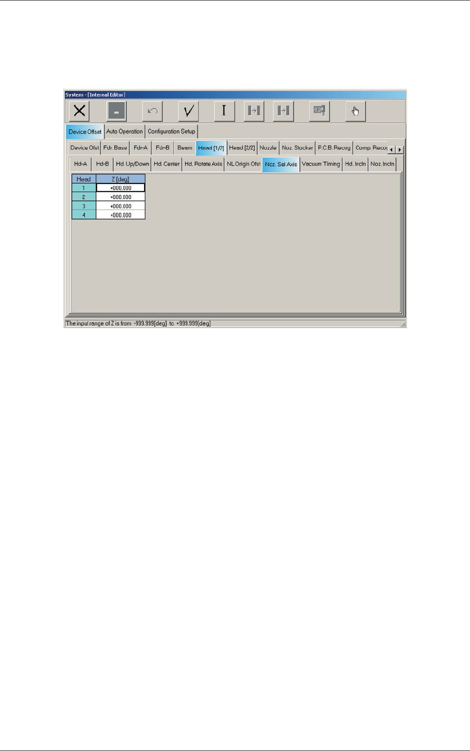
2.1.11 Nozzle Selection Axis Offset
When the "Head [1/2]" tab is pressed in the "Device Offset" tab sheet and the
"Noz. Sel Axis" tab is selected, the following tab sheet appears.
Fig. 3F27 "Noz. Sel Axis" Tab Sheet
Head 1, Head 2, Head 3, and Head 4
Z (Angle) [deg]
The se
t parameters are used to adjust the angular deviations between the
head rotational and nozzle selection axes.
0606-009
2.1 Device Offset Data
6-29
AIVEDT-ID
0606-009
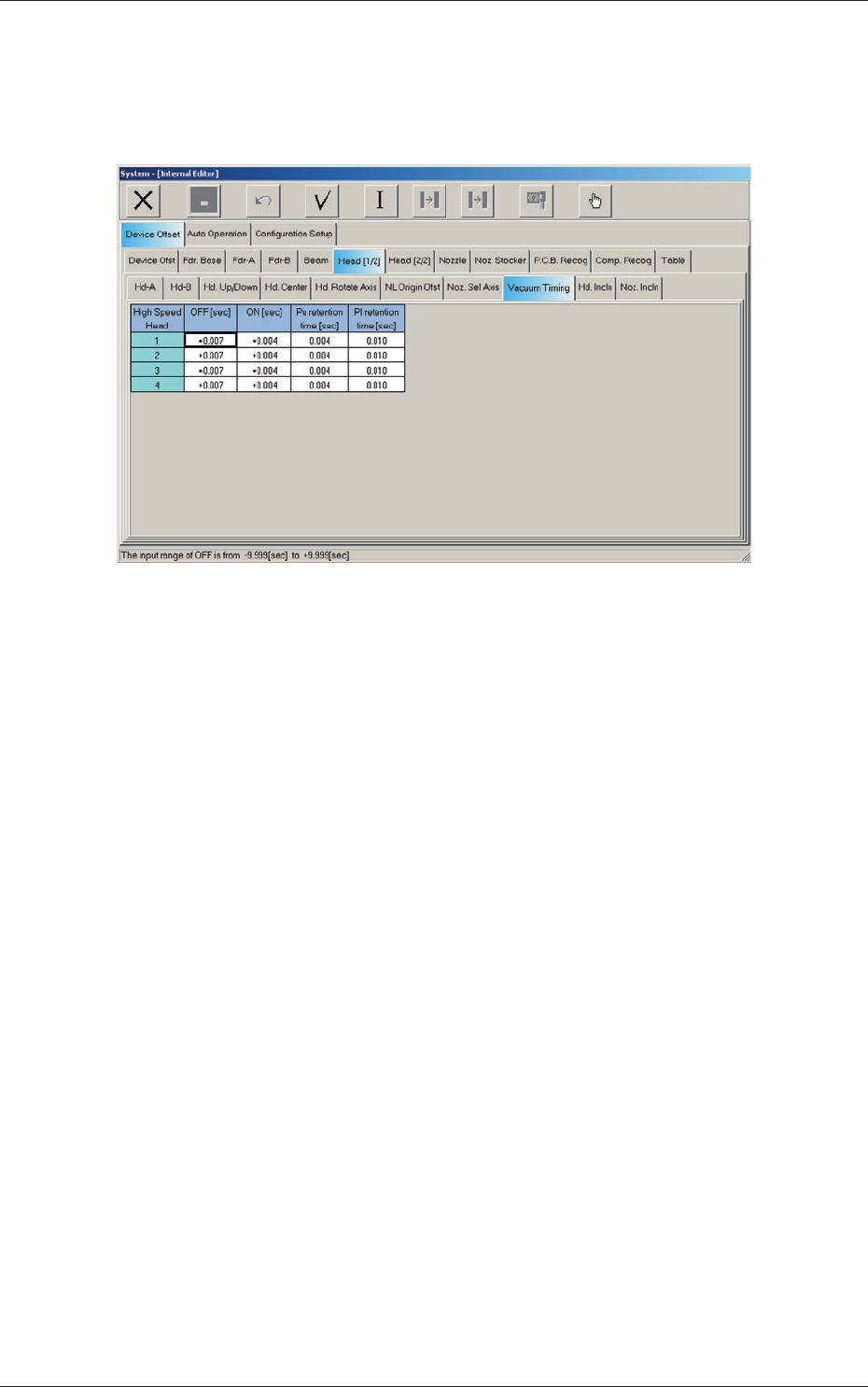
2.1.12 Vacuum Timing Offset
When the "Head [1/2]" tab is pressed in the "Device Offset" tab sheet and the
"Vacuum Timing" tab is selected, the following tab sheet appears.
Fig. 3F28 "Vacuum Timing" Tab Sheet
2.1 Device Offset Data