3OM-1208-011_w.pdf - 第272页
6-39 AIVEDT -ID 2.1.19 Master Nozzle Level Offset When the "Nozzle" tab is pressed in the "Device Offset" tab sheet and the "Master Nozzle Level" tab is selected, the following tab sheet app…
6-38
AIVEDT-ID
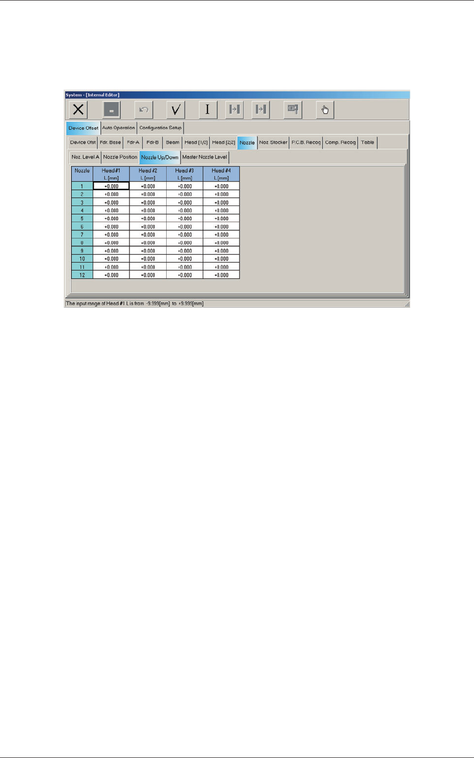
2.1.18 Nozzle Up/Down Offset
When the "Nozzle" tab is pressed in the "Device Offset" tab sheet and the
"Nozzle Up/Down" tab is selected, the following tab sheet appears.
Fig. 3F36 "Nozzle Up/Down" Tab Sheet
Nozzles 1 through 12
Head #1, Head #2, Head #3, and Head #4
L (Height) [mm]
The set parameters are the offsets based on the design value (gap)
between the upper surfaces of the nozzles and the nozzle U/D levers.
2.1 Device Offset Data
0606-009
6-39
AIVEDT-ID
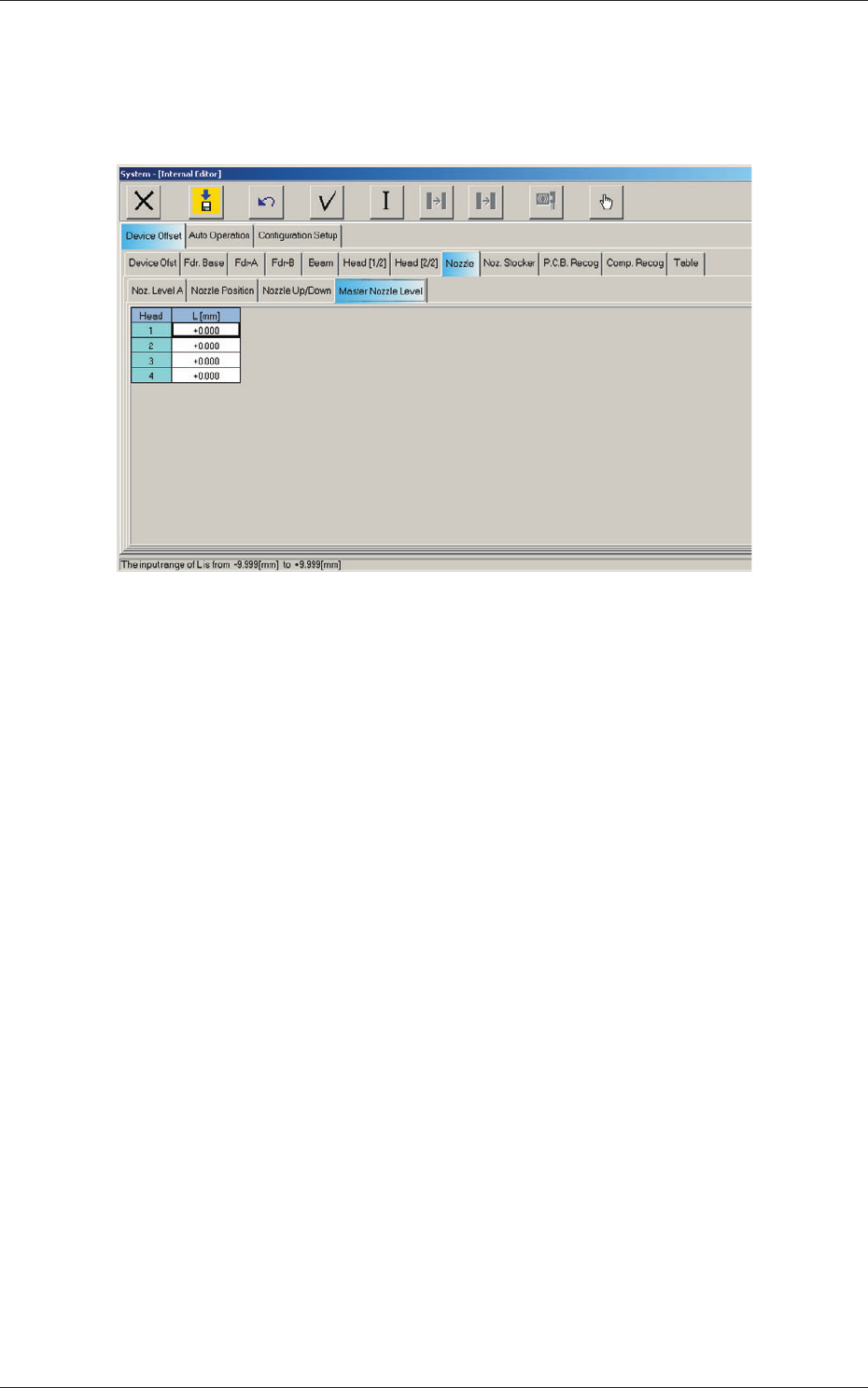
2.1.19 Master Nozzle Level Offset
When the "Nozzle" tab is pressed in the "Device Offset" tab sheet and the
"Master Nozzle Level" tab is selected, the following tab sheet appears.
Fig. 3F37 "Master Nozzle Level" Tab Sheet
Head 1, Head 2, Head 3, and Head 4
L (Height) [mm]
Each parameter indicates the reference position (the values read by the
linear measure) of the master nozzle bottom level.
Save the values of the master nozzle bottom level that was read by the
linear measure and used when the head up/down offsets were obtained
with the nozzle U/D axes being zeroed.
2.1 Device Offset Data
0606-009
6-40
AIVEDT-ID
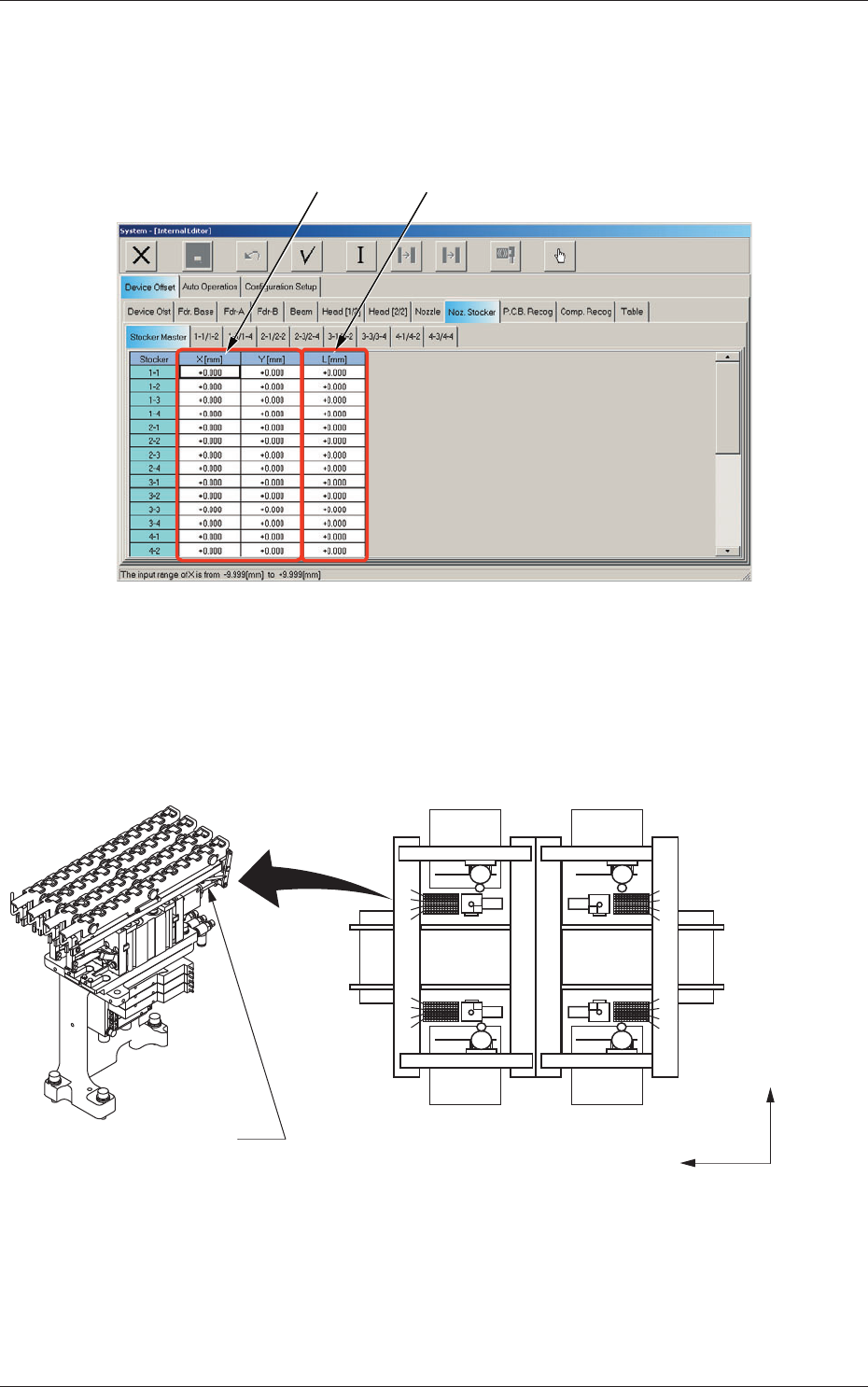
2.1.20 Stocker Master Offset
When the "Noz. Stocker" tab is pressed in the "Device Offset" tab sheet and
the "Stocker Master" tab is selected, the following tab sheet appears.
[1]
[2]
Fig. 3F38 "Stocker Master" Tab Sheet
Stockers
1-1 through1-4, 2-1 through 2-4, 3-1 through 3-4,
and 4-1 through 4-4
Placement Reference
X/Y Coordinate System
Y(+)
X(+)
2
1-4
1-3
1-2
1-1
2-1
2-2
2-3
2-4
3-4
3-3
3-2
3-1
4-1
4-2
4-3
4-4
4
3
2
1
1
2
3
4
5
6
7
8
9
10
11
12
(Front Side of Machine)
(Rear Side of Machine)
Nozzle Stocker A
4
3
1
Fig. 3F39
2.1 Device Offset Data
0606-009