3OM-1208-011_w.pdf - 第91页
3-4 AIVEDT -ID Z (Angle) [deg] Set the offset value for component placement angle. The set value is added to the " Offset Z (deg) " of all components in the placement data (P data). T o correct the angle of com…
3-3
AIVEDT-ID
(A01_03)
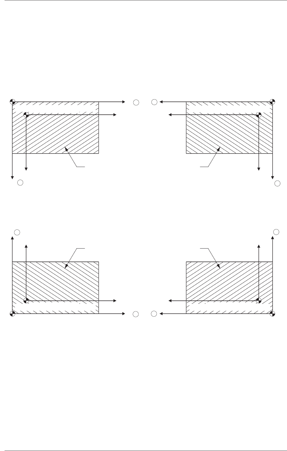
PCB origin offset
X (Horizontal), Y (Vertical) [mm]
Set the offset values to correct the difference between the placement
coordinate reference (N
0
) and the PCB origin (P
0
).
"
Plus
"
or
"
Minus
"
can be set in both X and Y coordinates in the
direction of the correction.
Placement Coordinate Reference Point :
For Front Right
Y
PCB Origin(P0)
PCB
X
Placement Coordinate Reference (N0)
PCB Origin(P0)
Y
X
Placement Coordinate Reference (N0)
X
Y
PCB
PCB Origin(P
0)
Placement Coordinate Reference (N0)
Y
X
PCB
PCB Origin(P
0)
Placement Coordinate Reference (N0)
Placement Coordinate Reference Point :
For Rear Left
Placement Coordinate Reference Point :
For Front Left
Placement Coordinate Reference Point :
For Rear Right
PCB
+
+
+
+
+
+
+
+
Fig. 3C3 Example of
"
+
"
(Plus) Direction for Correction
0606-009
1.2 Operation Data

3-4
AIVEDT-ID
Z (Angle) [deg]
Set the offset value for component placement angle.
The set value is added to the
"
Offset Z (deg)
"
of all components in the
placement data (P data).
To correct the angle of component placement counterclockwise, a
parameter must be entered with a plus (+) sign. A minus (-) sign must
be affixed for clockwise correction.
+.�
-.�
0�
Fig. 3C4
0606-009
1.2 Operation Data
3-5
AIVEDT-ID
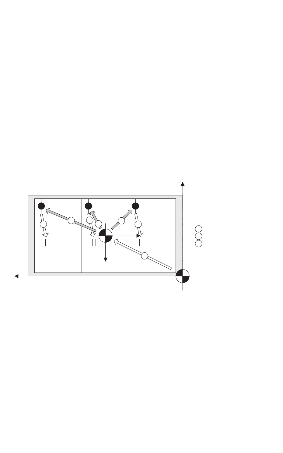
XY-Angle [deg]
Set the offset value for the angle between the machine coordinates
system and the placement coordinates reference system.
To correct the angle of component placement counterclockwise, a
parameter must be entered with a plus (+) sign. A minus (-) sign must
be affixed for clockwise correction.
X-Direction and Y
-Direction
"
Same
"
or
"
Opposite
"
can be selected as the X and Y directions in the
placement reference coordinate system.
Same :
Select this when the direction of the coordinates is
the same as that of the machine coordinates.
Opposite :
Select this when the direction of the coordinates
is opposite, compared with the direction of the
machine coordinates.
1
2
3
2
2
3
3
Y+
X+
X+
Y+
1 : PCB Origin Offset
2 : Unit PCB Origin
3 : Placement Coordinates
Machine Origin
PCB Origin
Machine Coordinate System
Machine Coordinate System
Placement
Coordinate
Reference
Fig. 3C5
Z Angular Orientation
Select one of the following options to determine the Z angular
orientation of the placement coordinate reference point.
Same :
Select this when the angular orientation is the same
as that of the machine coordinates.
Opposite
:
Select this when the angular orientation is opposite,
compared with the direction of the machine
coordinates.
0606-009
1.2 Operation Data