YSI_Prog_E.pdf - 第104页
2-33 2 Creating inspection pr ograms 3 Pr ess the [Add View] button to add a view . An added view appears red at a position slightly shifted to the lower right of the currently selected view. n NOTE Each view is displaye…
2-32
2
Creating inspection programs
2.6.4 Manual view creation procedure
If unable to convert to an inspection program due to such reasons as having no CAD data, it is necessary to
create views for positions at which inspection is to be performed, and create inspection steps inside these
views. This section describes how to create views. Views cannot be created with the optional iPro offline
software.
1
Press the [Data Edit] button and open the "View" tab.
TIP
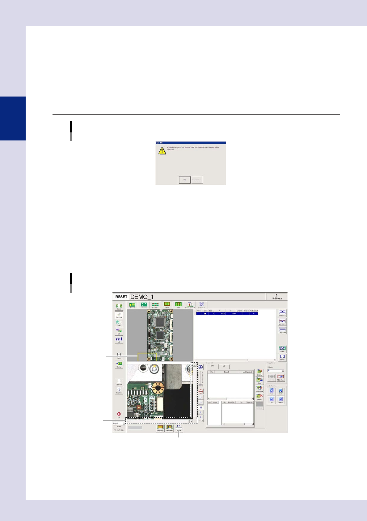
If there is no board in the inspection machine, and "View" or "Step" is selected, the following message appears. Press
the [No] button, set the board at the loading entrance sensor detection position, and press the [Change] button
Message
24230-P6-00
2
Move view 1 to the inspection position.
View 1 is created in the lower left of the view radar and is displayed in yellow. Use the following method
to move view 1 to the inspection position.
• Selectview1anddragwiththemouse.
• Usethescrollbar.
• Pressthe[0.1mm]movementpitchbuttontochangethepitch,andthenadjustwiththescrollbar
arrow buttons.
To shorten the camera movement time, allocate views from the edge of the board.
View image
Move view 1.
View 1
Scroll bar
[0.1mm] movement pitch button
24231-P6-00
2-33
2
Creating inspection programs
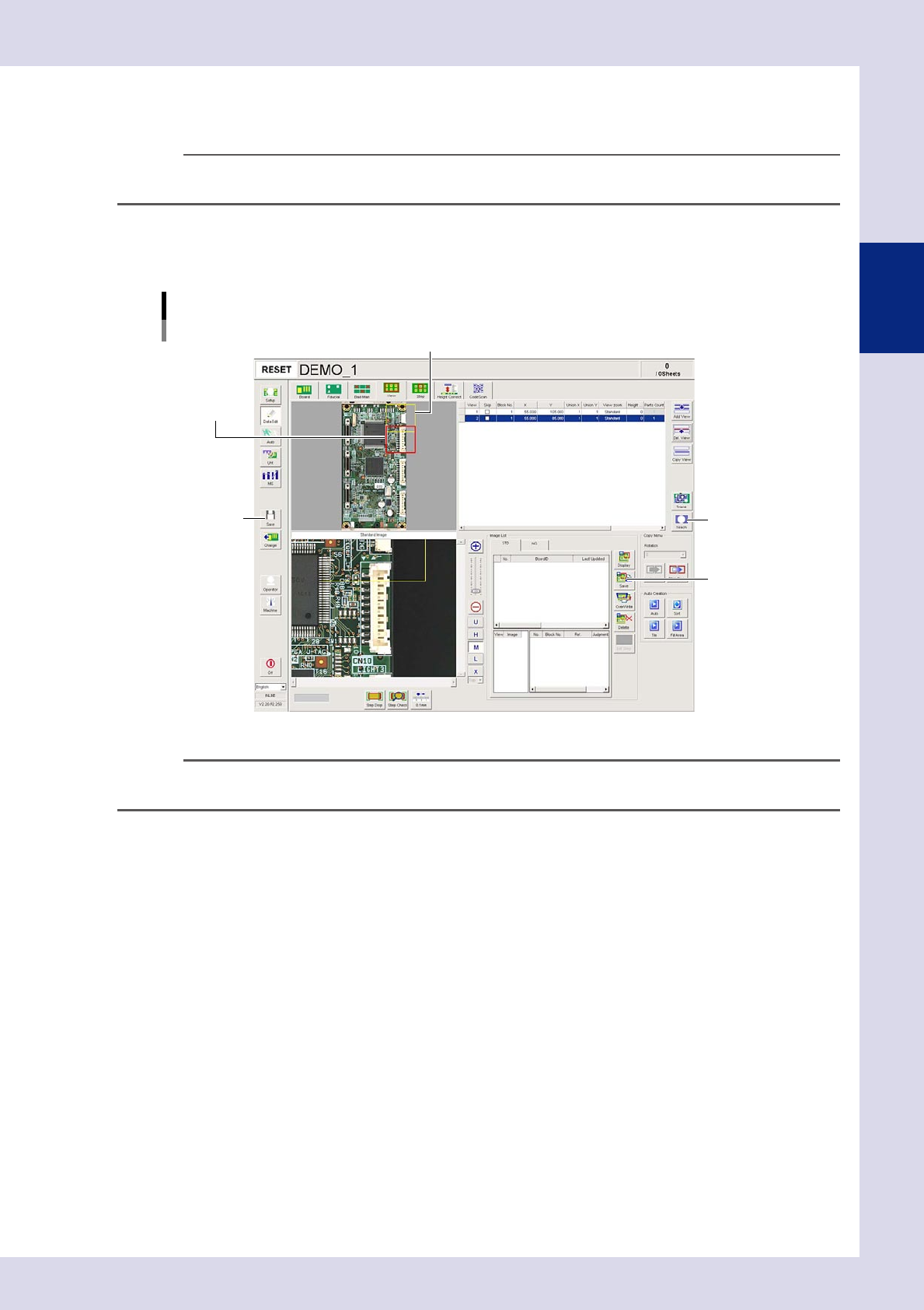
3
Press the [Add View] button to add a view.
An added view appears red at a position slightly shifted to the lower right of the currently selected view.
n
NOTE
Each view is displayed in color in the order that the views were created: yellow
→
red
→
green
→
blue
→
pink
→
purple
→
light blue. The selected view is highlighted by its color.
4
Move to the position at which the added view is to be inspected.
Move the added view to the desired inspection position by dragging it on the screen or using the scroll
bars or arrows.
View image
Adding views
Added view
View 1
Step6
Step7
Step8
24232-P6-00
n
NOTE
In order to avoid losing sight of the inspection area, an added view should be positioned so that it partially overlaps
the adjacent view.
5
Create views for all inspection positions.
Repeated Steps 3 and 4 to create views so that all locations to be inspected on the board are covered.
6
Press the [Teach] button.
Coordinates for the created view are registered.
7
Save the view image.
Open the image list "OK Image" tab and press the [Save] button. Press the [Yes] button at the
confirmation message that appears. Images for all views are captured and saved as standard images.
8
Save the inspection programs.
Press the [Save] button in the button area to save the inspection program.
2-34
2
Creating inspection programs
2.6.5 Multiple view operations
Multiple views selected on the view radar display can be copied, deleted, and rotated at the same time.
n
Selecting multiple views
1
Press the [Data Edit] button and open the "View" tab.
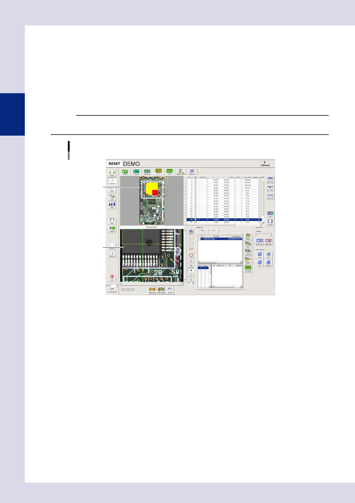
2
Select multiple views.
Enclose the multiple views to be selected in the view radar by dragging the mouse. The selected views
are shaded red and yellow. This time, the red-colored view is displayed in the view screen.
n
NOTE
By clicking the target multiple views in the view radar while holding down the keyboard [Ctrl] button, views can be
selected or deleted. This time, the view selected first is displayed in the view screen.
View image
Selecting multiple views
Selected view
Red view image
24233-P6-00