YSI_Prog_E.pdf - 第170页
4-10 4 Inspection status 8 Perform a step test again. 1. Press the [Step] button at the "T uning" tab again to per form a step test. 2. Take a n ote of and check the detection data, and then press the [End] but…
4-9
4
Inspection status
3
Set the "Judge" parameters.
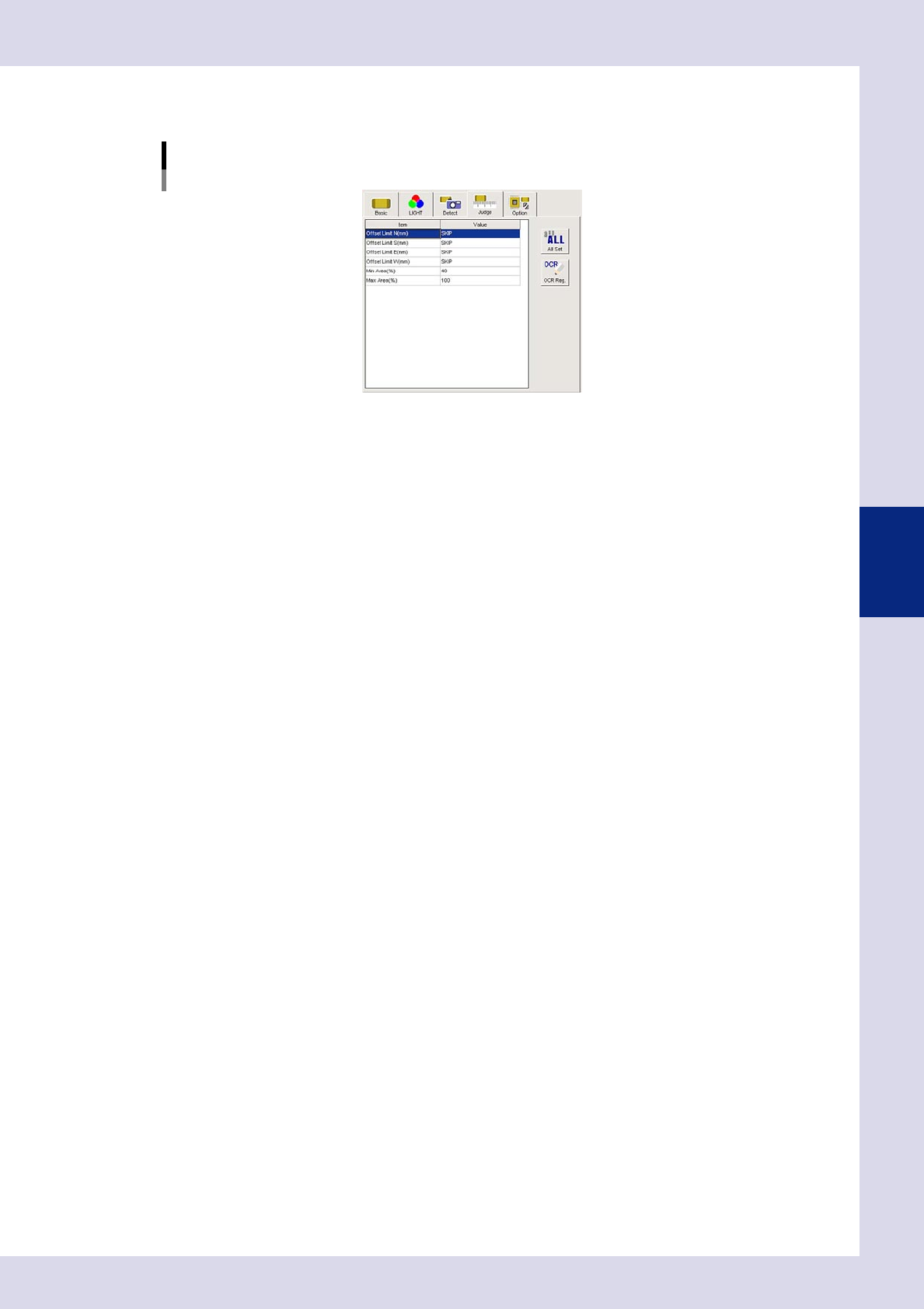
Open the "Judge" tab and set the following parameters.
"Judge" parameters
Status: Polarity Check
24413-P6-00
Offset Limit N, S, E, W (mm)
An NG result is judged if the positional displacement in the up, down, left, or right directions exceeds this
value.
Ref. value SKIP
Min Area (%)
If the ratio of the detected area to the standard area is smaller than the value set here, then an NG
occurs.
Ref. value 40%
Max Area (%)
An NG result is judged if the ratio relative to the standard area for the detected area exceeds this
value.
Ref. value 100%
4
Perform a step test.
1. Press the [Step] button at the "Tuning" tab to perform a test for the created step.
2. When the test result appears, press the [End] button. When doing so, there is no problem if the test
result is "NG".
5
Press the [Detail] button.
The "Inspect result" dialog box opens. Press the [Auto Calculation] button. The following items in the
detection conditions parameters are set automatically.
Minimum Detectable Size X
A value 50% of the recognized X width is set.
Minimum Detectable Size Y
A value 50% of the recognized Y width is set.
6
Change the step frame size.
Change "Step Size X, Y (mm)" in the basic parameters. To avoid a "permissible deviation error" due to the
influence of the polarity mark surroundings, enter a value to 1.5 to 2 times the polarity mark size.
7
Change the "Offset Limit" in the judgment conditions parameters.
Set "Offset Limit N, S, E, W (mm)" to "SKIP".
4-10
4
Inspection status
8
Perform a step test again.
1. Press the [Step] button at the "Tuning" tab again to perform a step test.
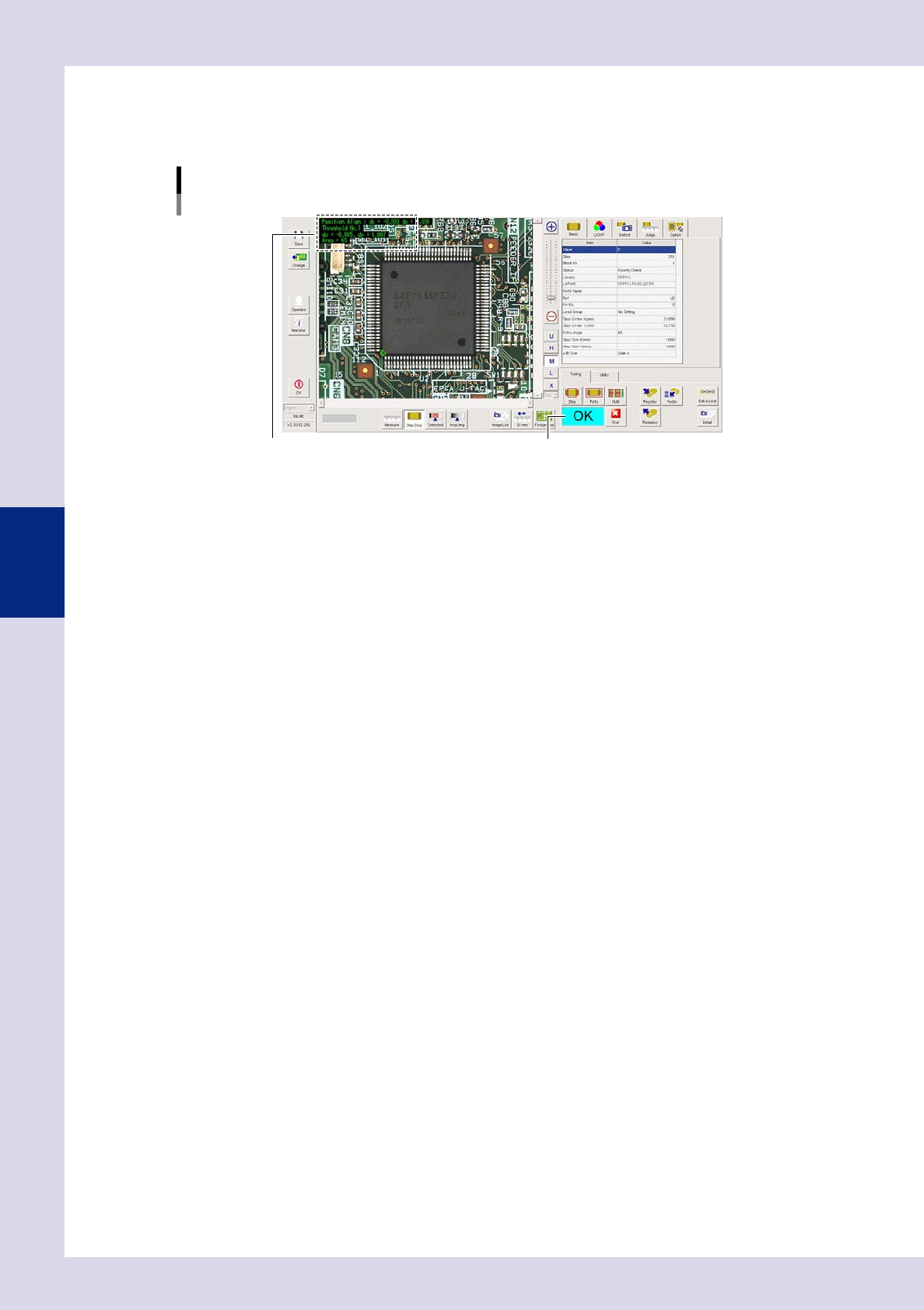
2. Take a note of and check the detection data, and then press the [End] button.
Screen after a step test is finished
Test resultDisplays detected data.
24414-P6-00
Detected data
Threshold No. : Threshold No. used for inspection
dx =, dy = : Amount that the step frame center deviates from the detection area center
Area = : Percentage of the detected area relative to the standard area
3. If the test result is not judged correctly, review all parameters while referring to the detection data.
4-11
4
Inspection status
1.4 Character Recognition
This inspection status is used if inspecting differences in parts types or the parts mounting angle for IC parts
and so on by recognizing characters on parts. Only upper case, alphanumeric characters can be recognized.
1
Make a "step" setting.
1. Create a step frame.
2. Open the "Basic" tab, and set the "Status" in the basic parameters to "Character Recognition".
3. Open the "LIGHT" tab, select the light sampling type, and set the threshold value to "AUTO" in the
lighting parameters so that characters are visible
Sampling light type reference: Luminance
Status (inspection mode)
Character Recognition
Set to "Character Recognition".
Step frame
24415-P6-00
n
NOTE
By selecting "AUTO" for the threshold value after setting the lighting, a test result can automatically be obtained with
the optimum threshold value. However, the inspection time will take a little longer than when the threshold value is
specified.
2
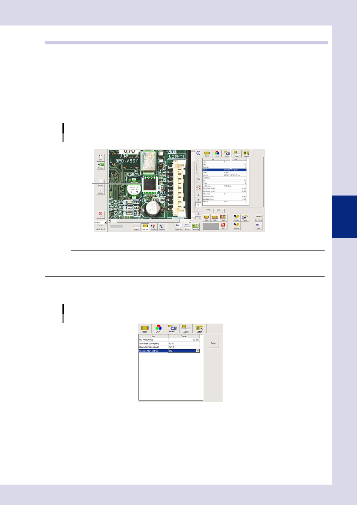
Set the "Detect" parameters.
Open the "Detect" tab and set the following parameters.
"Detect" parameters
Status: Character Recognition
24416-P6-00
Character Size X, Y (mm)
Set as follows : AUTO