YSI_Prog_E.pdf - 第71页
Chapter 2 Creating inspection programs Contents 1 1 1.2 Inspection method 2- 2 1.2.1 Optical inspection 2- 2 1.2.2 X-ray inspection 2- 4 …
1-35
1
asic operation
2.5 Ending the automatic inspection
After board inspections are completed, use the following procedure to exit the automatic inspection mode.
1
Ensure that the status is "waiting".
"Waiting" indicates that inspection is complete, and that the machine is waiting for the next board to be
loaded.
2
In the "Button" area, press the button for the next task.
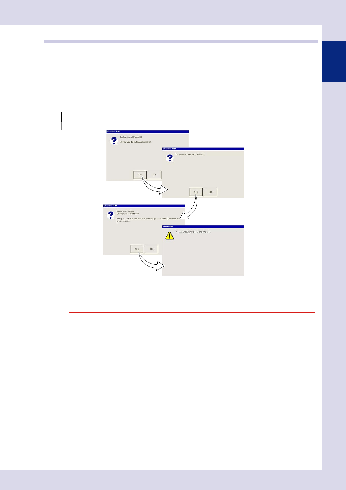
To end inspection machine operation, press the [Off] button. The following dialog box appears when
the [Off] button is pressed. Follow the instructions on the screen.
Power off dialog box
24136-P6-00
e
Pressing the emergency stop button exits the inspection machine application and Windows. When it is okay to
turn the power off, turn off the inspection machine main power.
c

Chapter 2 Creating inspection programs
Contents
1
1
1.2 Inspection method 2-2
1.2.1 Optical inspection 2-2
1.2.2 X-ray inspection 2-4
5
1.3.1 Inspection with optical camera 2-5
1.3.2 Inspection with X-ray camera 2-8
2. Creating inspection programs 2-9
9
0
2.3 Creating full board images 2-12
5
2.4.1 Basic parameters 2-16
2.4.2 Fiducial mark settings 2-18
2.4.3 Setting fiducial mark CUSTOM lighting 2-22
4
2.5.1 Basic parameters 2-25
2.5.2 Bad mark settings 2-26
9
2.6.1 Saving view images 2-29
2.6.2 Using view images 2-30
2.6.3 Creating all views and shortening inspection time 2-31
2.6.4 Manual view creation procedure 2-32
2.6.5 Multiple view operations 2-34
2.7 Step settings 2-38
2.7.1 Pasting libraries 2-38
2.7.2 Step creation procedure 2-40
2.7.3 Registering libraries 2-44
2.7.4 Deploying libraries 2-46
2.7.5 Checking libraries 2-48
2.7.6 Saving view images 2-49
2.8 Library details 2-50
2-1
2
Inspection data creation and tuning
1. Before creating inspection programs
This section describes aspects to be aware of before creating inspection programs.
1.1 Views and steps
"Views" and "steps" are the essential elements for creating inspection data, and are explained below.
n
View
A "view" refers to a single field-of-view captured by the camera and is used as an inspection range. The camera moves to
the set position to perform inspection, and so view frames should be arranged on the board locations to be inspected so
that all parts are covered. If converting mount data to inspection machine data, by selecting the "Auto Assign View" check
box in the "CVT" dialog box, views are created automatically based on the step positions. Furthermore, views can also be
created by pressing the [Auto] button in the "view" screen. For details on view creation, refer to section 2.6, "View
settings", in this chapter.
TIP
The view size (field-of-view) differs depending on the lens, and cannot be changed in the application settings. The
standard view size is approximately 44.6 (X) x 37.4 (Y) mm (19 μm), however, view sizes of 24.6 (X) x 20.6 (Y) mm (10 μm)
or 12.3 (X) x 10.3 (Y) mm (5 μm) are also available with an option.
View creation example
23201-P6-00
n
Step
A "step" is the minimum inspection area within a view. Inspection is performed inside the step frame (inspection area),
and so it is necessary to create steps at the location of the object to be inspected, select inspection items, and set
parameters such as detection conditions and judgment conditions. All steps required for inspection must be created for
each parts, and are registered as parts libraries.
Step creation example
Library
23202-P6-00