YSI_Prog_E.pdf - 第82页
2-11 2 Creating inspection pr ograms 3 Select the file to be conv erted and press the [C onvert] button. 1. A multi-board panel block No. setting confirmation dialog box appears. Check the contents and press the relevant…
2-10
2
Creating inspection programs
2.2 Data conversion
Mounter data for YAMAHA mounters is converted to inspection programs using a data conversion function.
n
NOTE
Before performing this operation, it is necessary to refer to Chapter 5, "2.7 Data conversion settings", and set the
required items at the "Data Conversion Setting" screen in the machine settings.
1
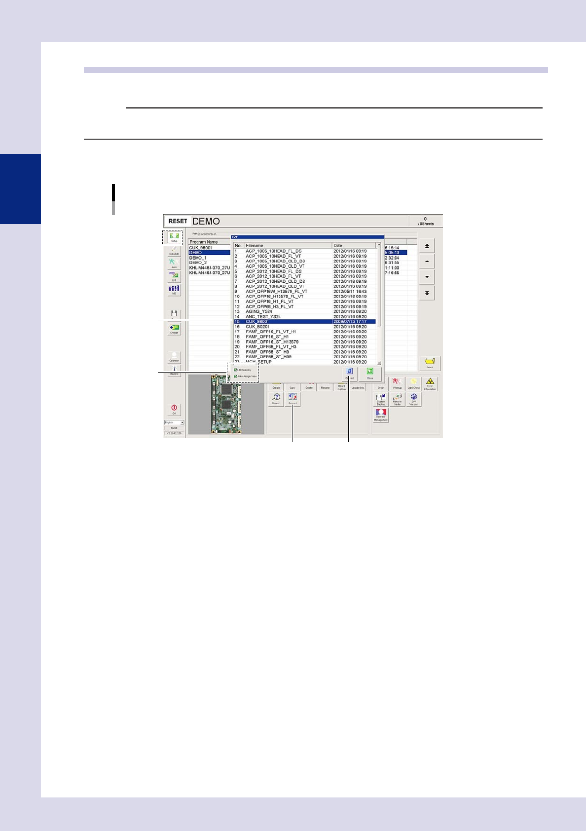
Open the "Setup" screen and press the [Convert] button.
A "CVT" screen appears.
[Setup] screen
Data conversion
[Convert] button [Convert] button
Step2
Step3
24205-P6-00
2
Set the conversion conditions.
Select both check boxes to enable the conversion conditions.
LIB Redeploy
By selecting this check box, libraries corresponding to the names of parts to be converted are deployed
to mounting positions based on the library table. If the selection is cleared, or parts name have not
been registered in the library table, steps are created for parts mounting positions without performing
library conversion.
Auto Assign View
By selecting this check box, views are created and assigned based on steps.
If the selection is cleared, views are not assigned.
2-11
2
Creating inspection programs
3
Select the file to be converted and press the [Convert] button.
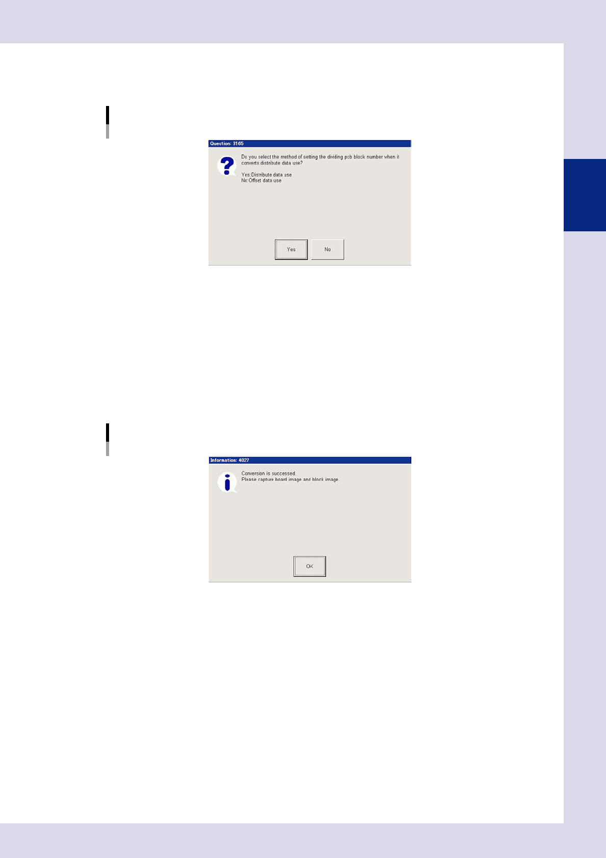
1. A multi-board panel block No. setting confirmation dialog box appears. Check the contents and
press the relevant button to perform data conversion.
Multi-board panel block No. setting confirmation dialog box
24206-P6-00
Yes
Uses reference data.
Select to convert data for blocks for which block deployment is complete.
No
Uses offset information.
Select to convert data for boards with only one block, or for boards for which no blocks have been
deployed.
2. A conversion complete dialog box appears when conversion is complete. Press the [OK] button to
return to the "Setup" screen.
Conversion complete dialog box
24207-P6-00
3. The name of the converted program appears in the status area, and the converted inspection
program is added to the program list.
2-12
2
Creating inspection programs
2.3 Creating full board images
If creating a new inspection program, it is necessary to create and save a full board image. Saved full board
images are used only as images for displaying the entire board, and are not used for inspection. This section
describes how to create full board images for inspection programs converted from YAMAHA mounter mount
data.
1
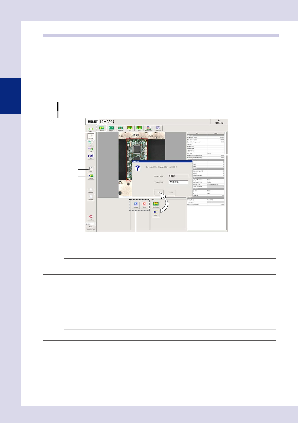
Press the [Data Edit] button and open the "Board" tab.
2
Press the [Width] button to change the conveyor width.
A conveyor width change dialog box appears. Ensure that the conveyor width after changing is the
same as "Board Size Y (mm)", and then press the [OK] button.
Conveyor width change
Step3
Step4
Step5
Step6
24208-P6-00
TIP
If using push up pins (option), set in positions where they will not interfere with the conveyor rails or other parts when
the push up plate is raised.
3
Press the [Change] button.
A confirmation dialog box appears. Place a board at the entrance and press [Yes]. The board is then
loaded and secured at the inspection position.
4
Press the [Execute] button.
The camera head moves at the specified pitch, an image of the board is captured, and a full board
image is created. Press the [Stop] button to cancel image capture.
n
NOTE
If the board size has not been entered in "Board Size X, Y (mm)", enter the correct board size.
5
Press the [Save] button.
Press the [Yes] button at the save confirmation dialog box that appears.