YSI_Prog_E.pdf - 第95页
2-24 2 Creating inspection pr ograms 2.5 Bad mark function T he bad mark function involv es affixing a mark (bad mark) to a set location on the board in order to cancel parts inspection when the mark is recognized b y th…
2-23
2
Creating inspection programs
5
Press the [Reduced Light] button to select the reduced light.
By pressing the [Reduced Light] button, a light sampling type screen appears. If required, select a single
image to be excluded from the reduced light list. (There is no need to make a selection.)
6
Select a noise cut filter.
This is used to eliminate noise. When noise is present, select the size to be averaged from the drop-down
list.
7
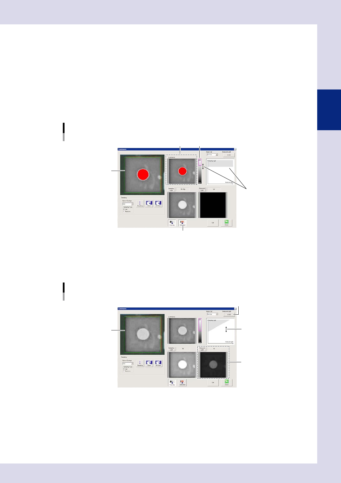
Press the [Detected] button and set the threshold value.
1. By pressing the [Detected] button, the detection range is displayed in color.
Adjust with the threshold slide bar and change the upper and lower limits to set the threshold so that
only the mark appears red.
Threshold value setting
Set by dragging the mouse.
Threshold value image
Threshold value image Threshold slide bar
[Detected] button
24219-P6-00
2. If reduced light is selected at Step 5, set the reduced light magnification. Set the magnification for
the reduced light selected when performing image processing to show only the mark in red. Press
the magnification button and enter the magnification, or drag the gray area on the monitor with the
mouse to set.
Reduced light magnification setting
Reduced light magnification setting button
Set by dragging the mouse.
Sampling light image
Reduced light image
24220-P6-00
8
End lighting setting.
To save settings, press the [Set] button followed by the [Close] button. To end without saving, press the
[Close] button. By pressing the [Close] button, the display returns to the fiducial screen.
2-24
2
Creating inspection programs
2.5 Bad mark function
The bad mark function involves affixing a mark (bad mark) to a set location on the board in order to cancel
parts inspection when the mark is recognized by the inspection machine.
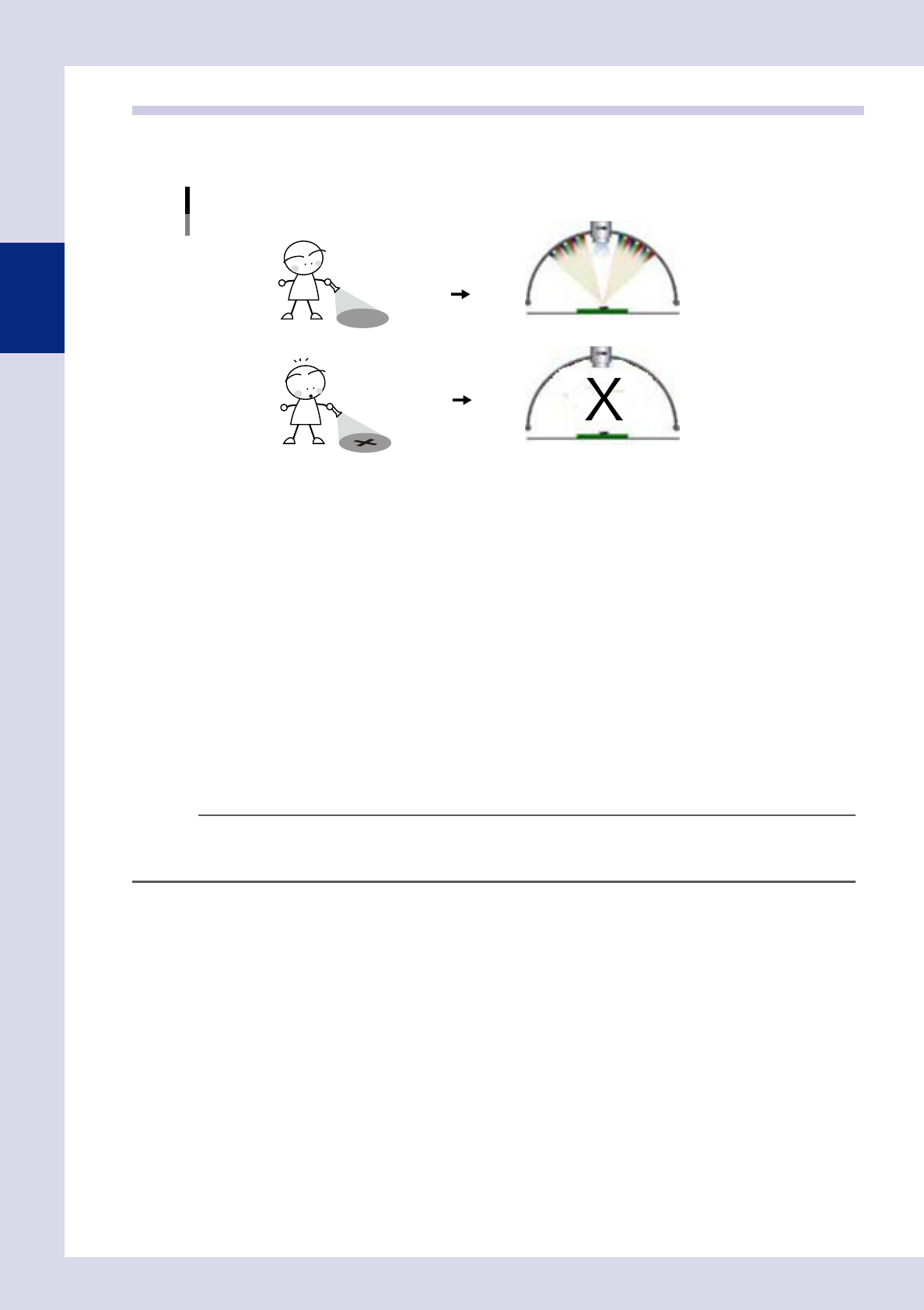
Bad mark function
Parts are inspected when no bad mark is detected.
Parts are not inspected when a bad mark is detected.
23215-P6-00
The following three types of bad mark are available. Use these bad marks accordingly depending on the
purpose.
n
Board bad mark
A bad mark is assigned to each board, and is used to judge whether the inspection machine searches for a bad mark. If,
for example, there is a mix of multi-board panels, some with defective blocks and some without, being transfered on the
conveyor, it will be a waste of time to search for bad marks on all boards even when there are no defective blocks. By
using the board bad mark function, a search is only performed for bad marks if a board bad mark is recognized. When
not recognized, an unconditional parts inspection is performed for all blocks.
n
Block bad marks
Bad marks are set for each block, and block inspection is skipped if the machine detects a bad mark. If, for example, no
parts have been mounted on block B (defective block) on a multi-board panel comprising blocks A, B, C, and D, a bad
mark is affixed to the board for block B. The inspection machine searches for bad marks on all blocks prior to inspection,
inspection of block B on which the bad mark was recognized is canceled, and parts inspection is performed only for
blocks A, C, and D.
TIP
If block bad marks exist in the inspection view field-of view, by performing mark recognition in the same view as step
inspection without performing axis movement only for bad mark recognition during auto inspection, inspection tact
time is reduced. When editing data, the camera moves to all bad mark positions to perform recognition.
n
Local bad marks
Bad marks are set for each step, and step inspection is skipped if the machine detects a bad mark.
2-25
2
Creating inspection programs
n
Bad mark screen
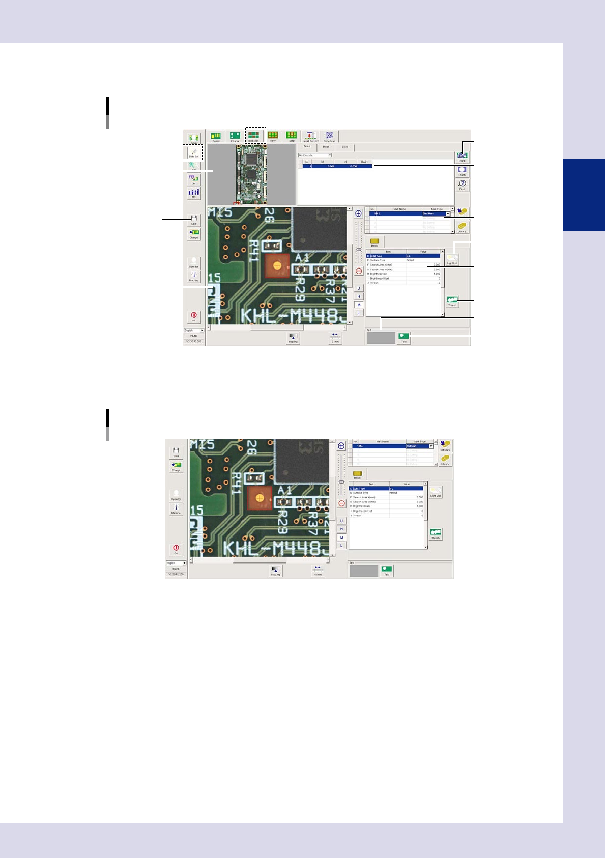
By pressing the [Data Edit] button and opening the "Bad Mark" tab, the following bad mark setting screen appears.
[Bad Mark] tab screen
[Trace] button
[Light List] button
[Thresh] button
[Test] button
[Save] button
Recognition results
Field-of-view image
Basic parameters
Mark data list
Mark list
Board image
24221-P6-00
2.5.1 Basic parameters
Basic parameters
24256-P6-00
D. Light Type
Selects the lighting used to recognize the mark.
E. Surface Type
Select "Reflect" or "Non-reflect" from the drop-down list based on the mark being used.
F, G. Search Area X, Y (mm)
Sets the size of the area in which to search for the mark. The value can be entered from 0.00 to 150.00 (unit: mm). The
presence of bad marks is judged based on whether the inside of the detection range is reflective or non-reflective, and
therefore a range smaller than the size of the mark is set.
H. Brightness Gain
Adjust this value to brighten the entire image so that the mark is easily recognized.
I. Brightness Offset
Adjust this value to make the entire image darker so that the mark is enhanced.
J. Thresh
Press the [Thresh] button to set the threshold value for mark detection.