YSI_Prog_E.pdf - 第113页
2-42 2 Creating inspection pr ograms 6 Select the lighting. Select a lighting for solder fillet recogn ition. If inspecting the solder fillet solder quantity, press the [Sampling Light] button to open a "Sampling Li…
2-41
2
Creating inspection programs
4
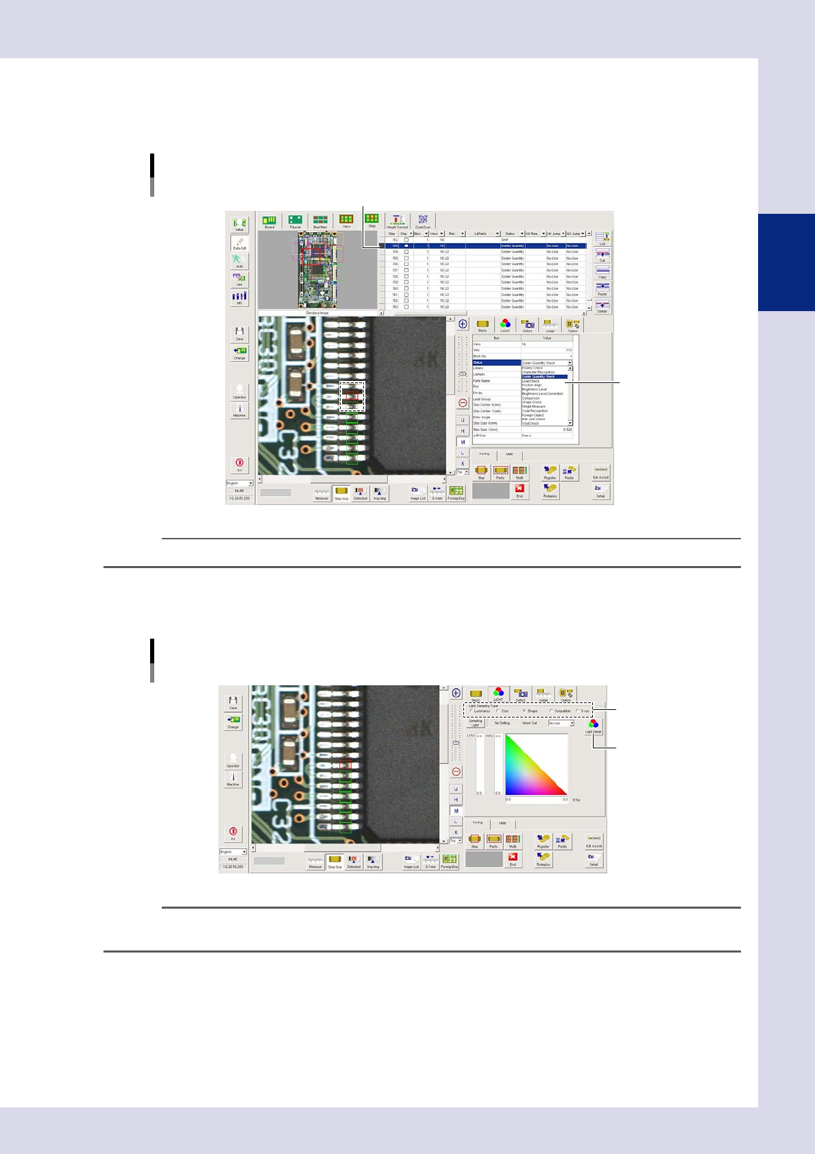
In the "Basic" parameter list, set the "Status" (inspection mode).
Select the inspection mode used to inspect the objects in the created step frame.
Select "Solder Quantity Check".
[Data Edit] - [Step] screen
Step creation
Created step
Select "Status"
(inspection mode).
24241-P6-00
TIP
For details on the inspection status and related parameters, see Chapter 4, "Inspection status", in this manual.
5
Open the "LIGHT" tab and select the "Light Sampling Type".
If inspecting the fillet solder quantity, click the "Shape" radio button.
[Data Edit] - [Step] screen
[LIGHT] tab settings
Sampling light type
[Light Detail] button
24242-P6-00
TIP
For details on the light sampling type, see Chapter 3, "2.1 Recognition method (based on light sampling type)", in this
manual.
2-42
2
Creating inspection programs
6
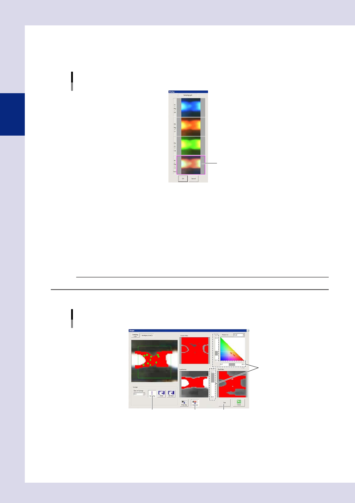
Select the lighting.
Select a lighting for solder fillet recognition. If inspecting the solder fillet solder quantity, press the
[Sampling Light] button to open a "Sampling Light"selection dialog box, select "Hr+Mg+Lb Ver2" from the
sampling light list, and then press the [OK] button.
Shape: [Sampling Light] - "Sampling Light" selection dialog box
Select the lighting.
24246-P6-00
7
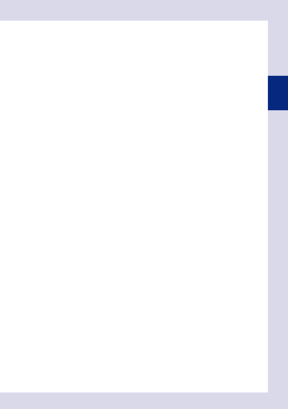
Set the threshold value.
Set the threshold value used to show the solder fillet in red.
1. Press the [Light Detail] button to open the "Shape" screen.
2. Press the [Sampling] button, and then click the location to be detected in the upper left image. The
clicked gradient area is shown in red. Click until most of part of the fillet turns red.
3. Press the [Sampling] button again to end sampling.
4. Press the [Detected] button.
5. Adjust the three threshold slide bars to show the object to be inspected in red. The common areas
shown in red in the three images are shown in red in the upper left image.
TIP
The threshold value can also be adjusted with the threshold slide bars without performing sampling.
6. Press the [Set] button to return to the "Step" screen.
Threshold value setting: shape
[Sampling] button
Threshold slide bar
[Detected] button [Set] button
24249-P6-00
2-43
2
Creating inspection programs
8
Set the detection conditions.
The setting items will differ for each inspection status.
Refer to Chapter 4, "Inspection status", and set the detection conditions.
9
Set the judgment conditions.
The setting items will differ for each inspection status.
Refer to Chapter 4, "Inspection status", and set the judgment conditions.
0
Perform a step test.
Press the [Step] button at the "Tuning" tab, and perform a step test.
If the test result is not judged to be correct, review all parameters.
q
Repeat the above procedure to create steps.
Repeat the procedure described in Step 2 to Step 11 and create steps for all parts to be inspected.
w
Register the created steps in a library and then deploy.
When the creation of all steps for the inspection of a single part is complete, register them as a library,
and then deploy to to the same parts on the board. For details on this procedure, see section 2.7.3,
"Registering libraries", and 2.7.4, "Deploying libraries", described later.