YSI_Prog_E.pdf - 第150页
3-27 3 Step screen 2.4.2 Measurement results By pressing the [Detail] button following a step test, a "T est Results" screen appears containing data for detected areas within steps. "T est Results" sc…

3-26
3
Step screen
Changes the display.
Display by Ref. No.
Ref. No. unit (part unit) test results are displayed in the left side list of the inspection list. By selecting parts from
the list, the selected row is highlighted in blue, and the step test result for the applicable part is displayed in the
right side list of the inspection list. Select a step and check the step position and parameters.
Display by Step:
Displays the test results for all tested steps. Select a step and check the step position and parameters.
NG Parts Count
Displays the number of parts for which the test result is NG.
NG Steps Count
Displays the number of steps for which the test result is NG.
[Analysis] button
By selecting a display item, the test result for the relevant item is displayed in a graph. Refer to this when setting
parameters for data tuning.
5
Press the [Close] button to exit the multi-test.
3-27
3
Step screen
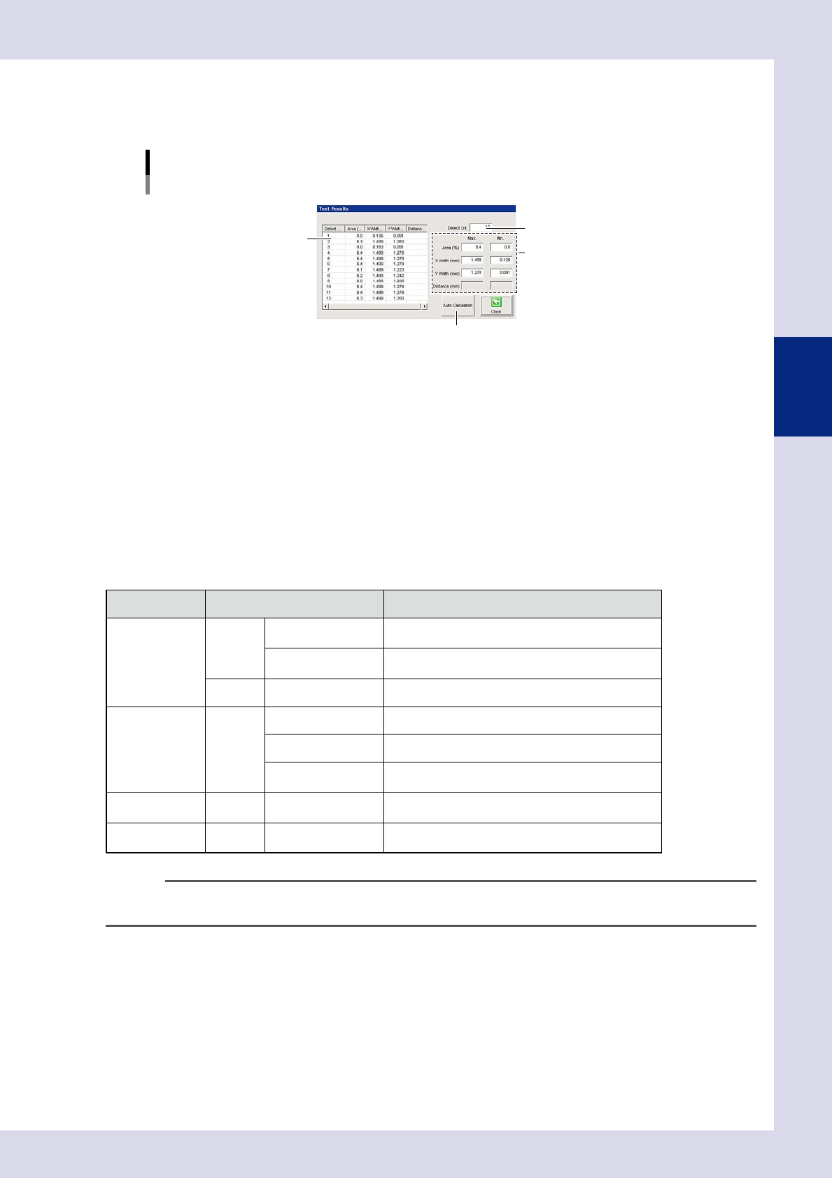
2.4.2 Measurement results
By pressing the [Detail] button following a step test, a "Test Results" screen appears containing data for
detected areas within steps.
"Test Results" screen
Inspection mode: "Lead Check"
3
2
1
4
24332-P6-00
1. Detection area details
Shows the details of all detection areas within the step. Recognized characters and corresponding scores are displayed
following a character recognition test.
2. Detect count
Shows the number of detected steps and number of inspection steps.
3. Max. / Min.
Displays the "Area", "X Width", and "Y Width" maximum and minimum values.
4. [Auto Calculation] button
By pressing this button, detection condition setting values change to appropriate values automatically based on the
detection area. The locations which change and appropriate value calculation method differ for each inspection status.
The items that are automatically set by pressing the [Auto Calculation] button are as follows.
Status Parameters Setting value
Lead Check Judge
Maximum Acceptable
Size X, Y
1.5 times the maximum size XY of each detected lead
Lead Width Check
0.7 times the minimum size of each detected lead when
this parameter is enabled.
Detect Std Area Step area
Electrode Check Detect Std Area Sum of two electrode areas
Minimum Area Fixed to 20%
Minimum Detectable
Size X, Y
0.7 times the step frame size
Character
Recognition
Detect Character Size Maximum detectable size XY by character recognition
Parts Check Detect
Minimum Detectable
Size X, Y
0.7 times the step frame size
n
NOTE
Values entered by pressing the [Auto Calculation] button cannot be applied to all parts. If a step test is performed
and the test result is not incorrect, change the parameter settings as required.
3-28
3
Step screen
3. Editing Assistance
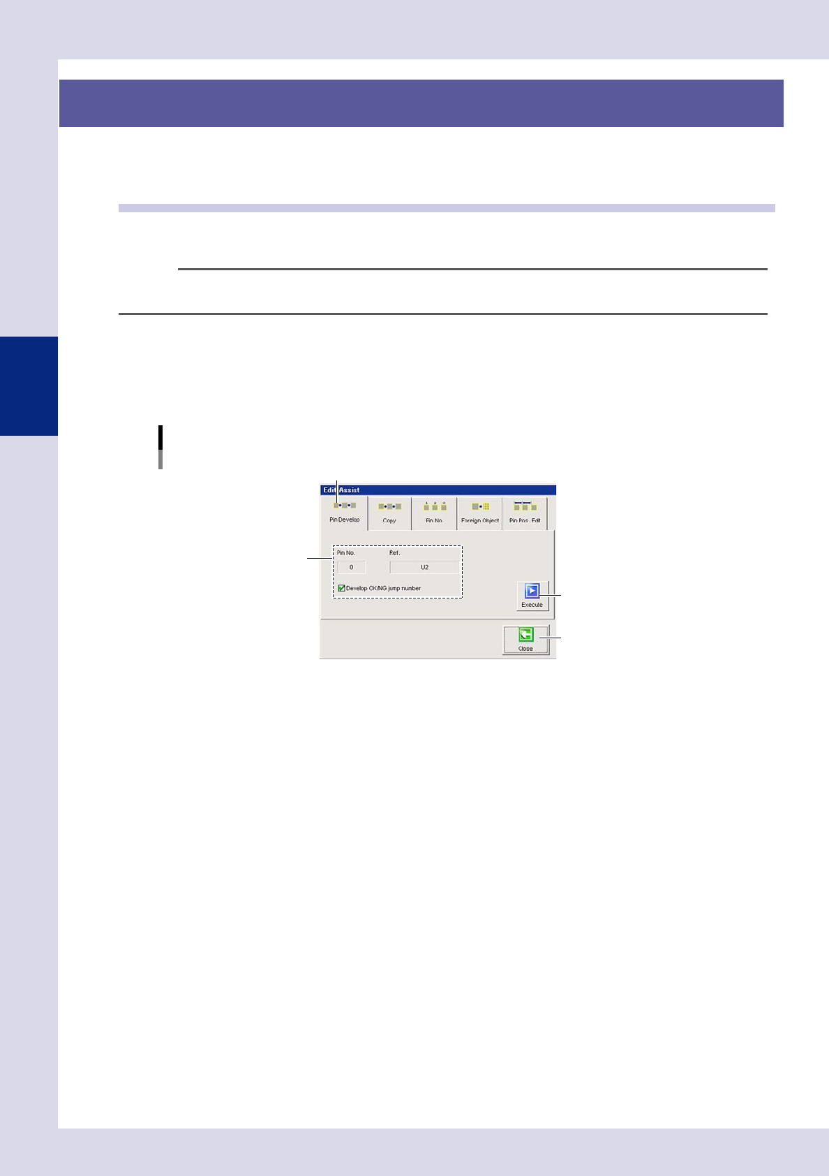
By press the [Edit Assist] button at the "Tuning" tab, an "Edit Assist" screen used to create steps efficiently
appears. This section describes operations that can be performed at the "Edit Assist" screen.
3.1 Pin Information Deployment
Pin information deployment is used when changing parameters for steps in which leads with set pin Nos. are
inspected by deploying parameters for inspection of other leads on the same parts to the same settings.
TIP
In order to deploy pin information, the "Ref. No." and "Pin No." must be set correctly for all relevant steps in the basic
parameters.
1
Select a step.
Select the deployment source lead step at the "Step" screen.
2
Press the [Edit Assist] button and open the "Pin Develop" tab.
A screen used to set the deployment of pin information appears.
Editing assistance
Pin information deployment
Step 3
[Execute] button
[Close] button
"Pin Develop" tab
24333-P6-00
3
Check the Pin No. and Ref No.
The Pin No. and Ref No. for the step selected at Step 1 are displayed. Verify that they are correct. To
deploy the OK/NG jump number, select the "Develop OK/NG jump number" check box.
4
Press the [Execute] button.
The inspection parameter settings for all leads on the same parts will be the same for the lead
parameters selected at Step 1.
5
Press the [Close] button to end deployment.