YSI_Prog_E.pdf - 第98页
2-27 2 Creating inspection pr ograms 4 Mo ve the camer a to the fiducial mark position. Select a mark from the mark list and pr ess the [Trace] button. The camera moves to the fi ducial mark position. 5 Enter the mark da…
2-26
2
Creating inspection programs
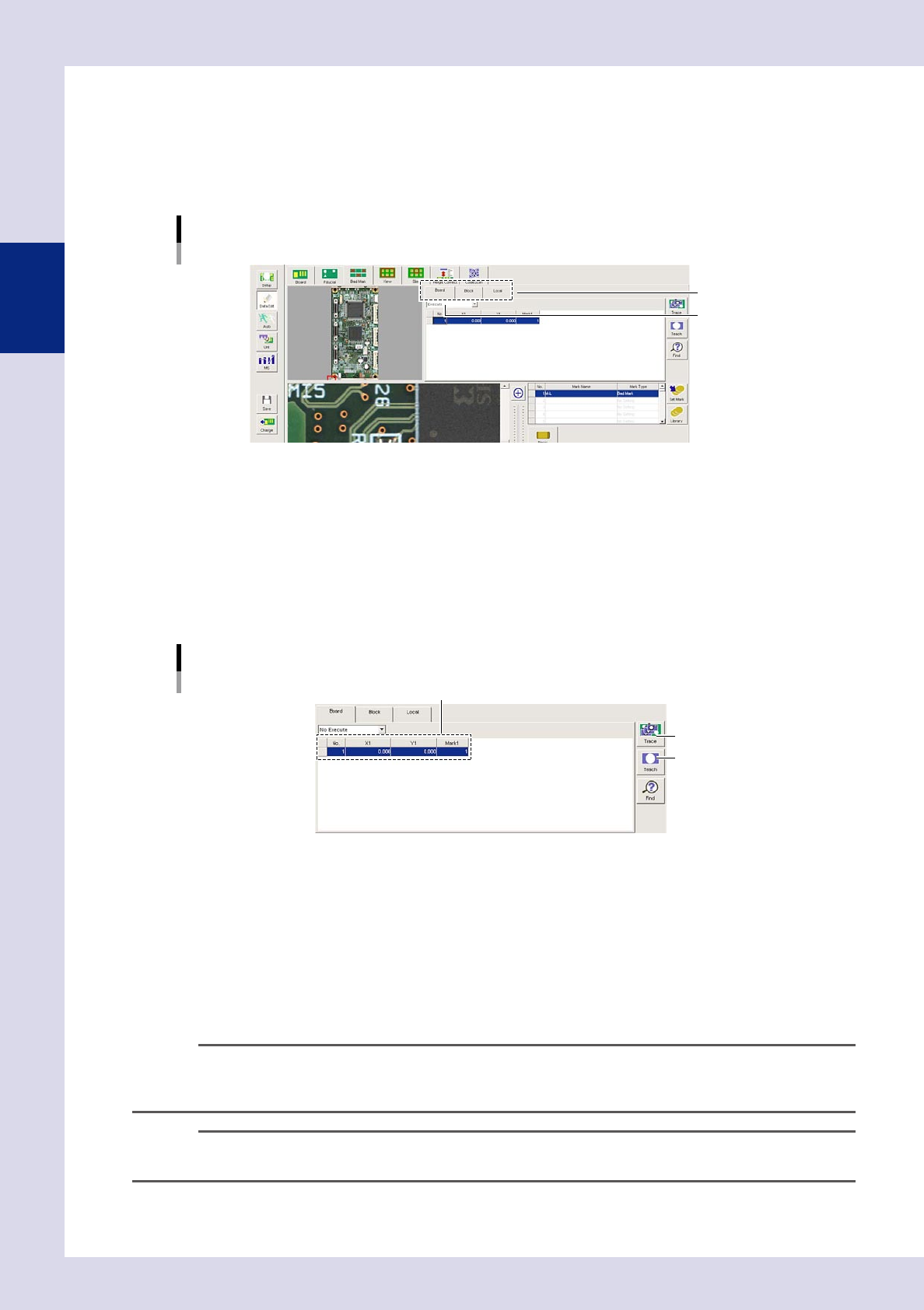
2.5.2 Bad mark settings
1
Press the [Data Edit] button and open the "Fiducial" tab.
2
Set bad marks
Open the tab for which fiducials are to be set, and set the fiducial function to "Execute".
Bad mark settings
Select a tab.
Set to "Execute".
24222-P6-00
"Board" tab (board bad mark)
Set when using the block bad mark or local bad mark function.
"Block" tab (block bad mark)
Skips inspection of each block.
"Local" tab (local bad mark)
Skips inspection of arbitrary steps.
3
Set the mark list.
Mark list settings
[Teach] button
XY coordinates, mark Nos.
[Trace] button
24223-P6-00
X1, Y1
Enter the bad mark coordinates. If bad mark coordinates are unknown, coordinates can be entered by
teaching. After clicking the bad mark on the board image, click the center of the bad mark in the
field-of-view image. After setting the mark parameters, press the [Teach] button when the test result is
"OK". The recognized center coordinates are entered.
Mark 1
This number corresponds to the number in the mark data list, and therefore a mark No. for which no
fiducial mark has been set should be entered.
n
NOTE
• Ifsettingblockbadmarks,setthebadmarkinthelineforeachblockNo.
• Ifsettinglocalbadmarks,settherespectivelocalducialmarks.Setthemarklistnumberforthe"G.LocalBad
Mark No." optional parameter for the relevant step.
TIP
If the bad mark is unclear, use the U, H, M, or L lighting buttons to change the lighting so that the mark becomes
clearer.
2-27
2
Creating inspection programs
4
Move the camera to the fiducial mark position.
Select a mark from the mark list and press the [Trace] button. The camera moves to the fiducial mark
position.
5
Enter the mark data list.
Set for the mark No. set in mark 1 in the mark list.
Mark data list settings
Select bad mark.
Set for mark 1 No.
24224-P6-00
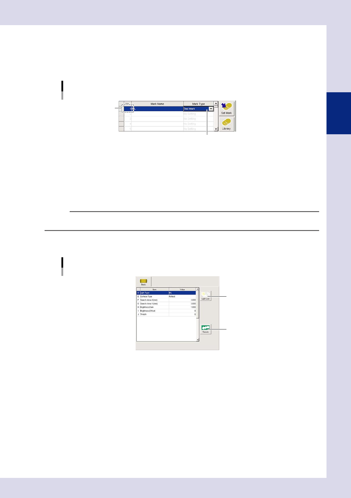
No.
This number corresponds to the mark No. set in mark 1 in the mark list.
Mark Name
Enter an easily distinguishable name up to nineteen single-byte alphanumeric characters for each mark.
Spaces cannot be entered.
Mark Type
Select "Bad Mark" from the drop-down list.
TIP
"Fiducial", "Bad Mark", and "Code Scan" can be set in the mark list, and so the code No. should be changed when
registering.
6
Set the basic parameters.
Set the following parameters.
[Bad Mark] tab screen
Basic parameter
[Light List] button
[Measure] button
24225-P6-00
E. Surface Type
Select from the drop-down list based on the bad mark being used.
F, G. Search Area X, Y (mm)
Enter the size of the area in which to search for the mark.
H. Brightness Gain, I. Brightness Offset
Set so that the marks on the board are clearly visible.
2-28
2
Creating inspection programs
7
Press the [Light List] button and select a clear image.
By pressing the [Light List] button, a list of images appears. Select an image in which the mark appears
clearly from the image list, and press the [Set] button. When setting is complete, the display returns to
the "Bad Mark" screen, and the "D. Light Type" is set.
8
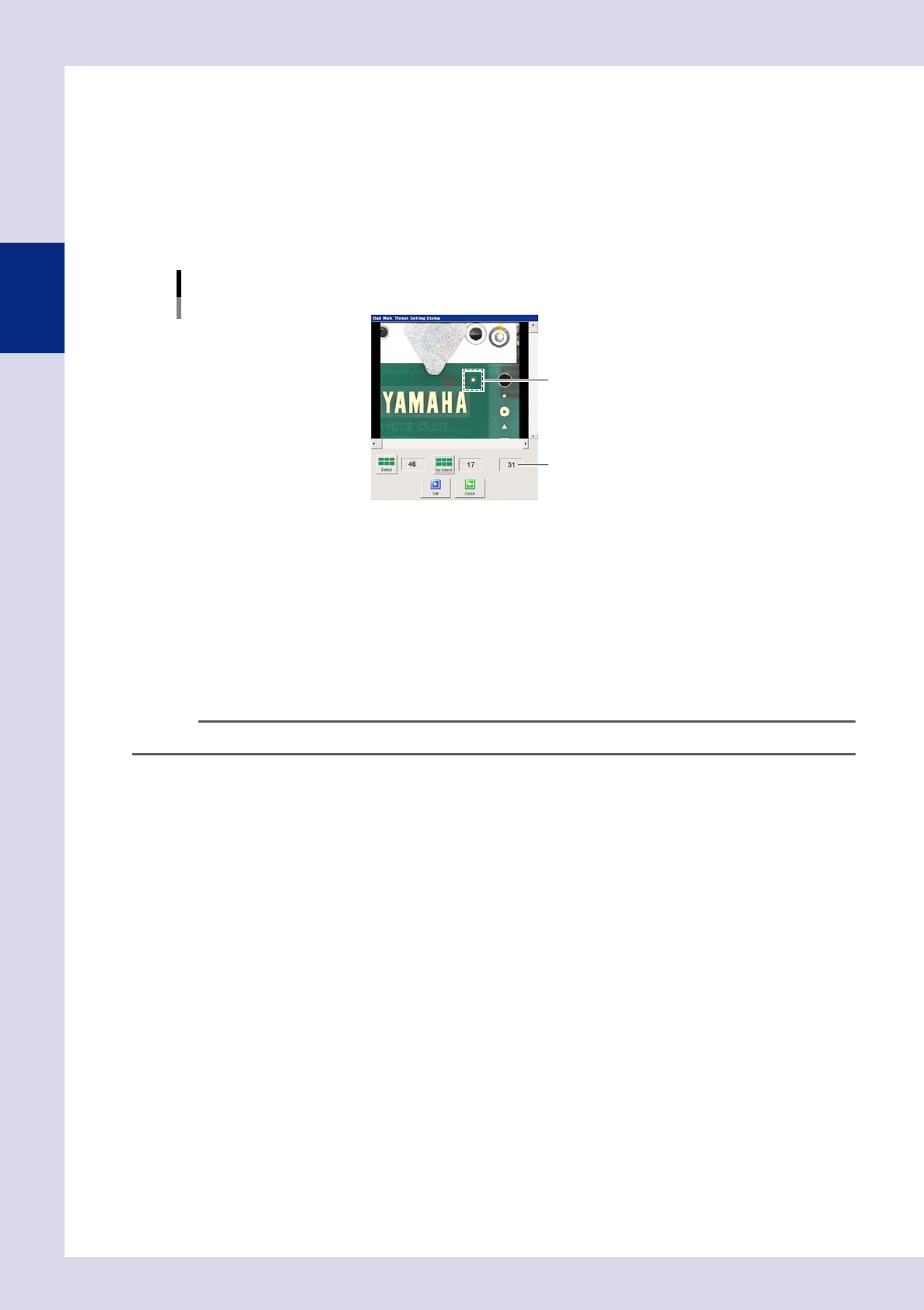
Press the [Thresh] button and set the threshold value.
By pressing the [Thresh] button, a "Bad mark threshold value setting" screen appears. Set the threshold
value using the following procedure.
1. Click the bad mark on the screen, and move the camera axis until the mark enters the red box.
"Bad mark threshold value setting" screen
Threshold value
Select the bad mark.
24226-P6-00
2. Press the [Detect] button to display the luminance when a bad mark exists.
3. Click a position with no bad mark, and move the camera axis to a position with no marks.
4. Press the [No Detect] button to display the luminance when no bad mark exists.
5. The intermediate value is set as the threshold value. Press the [Set] button to set the value for "J.
Thresh". By pressing the [Close] button without pressing the [Set] button, the acquired threshold value
is not set.
9
Perform a test.
Press the [Test] button to verify whether the mark is judged correctly.
TIP
The mark recognition coordinates appear in the upper left of the mark screen.
0
Press the [Save] button to save the inspection program.