YSI_Prog_E.pdf - 第76页
2-5 2 Inspection data creation and tuning 1.3 Main inspection items T his section describes the inspection status and judgment method required to perform inspection by main items that YSi Series machines are capable of i…
2-4
2
Inspection data creation and tuning
1.2.2 X-ray inspection
X-ray inspection is used to inspect solder joints on lower surface electrode parts and the back fillet of leaded
parts, and solder on parts mounted on the lower surface. Tomographic imaging is possible with digital
laminography, and so height inspection can be performed with height set. Inspection is performed by
compensating for board warp, and therefore laser unit height measurement is used. The resolution can be
changed to 12, 19, 27, and 54 μm for each field-of-view based on the size of the inspection object.
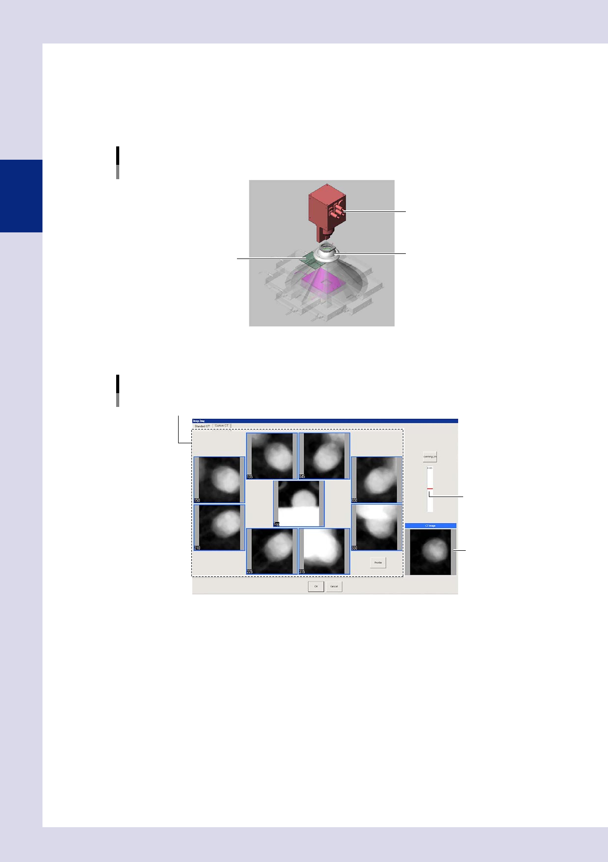
Inspection image selection image
X-ray source
Dome lighting
Board
23204-P6-00
X-ray inspection involves setting the inspection height and creating X-ray horizontal tomographic images based
on an aerial X-ray image and X-ray images from up to eight different directions.
X-ray inspection image
Inspection image
Set the insection height.
Aerial (center) image, images from eight directions
24202-P6-00
2-5
2
Inspection data creation and tuning
1.3 Main inspection items
This section describes the inspection status and judgment method required to perform inspection by main items
that YSi Series machines are capable of inspecting. For details on the inspection status, see Chapter 4,
"Inspection status", in this manual.
1.3.1 Inspection with optical camera
n
Missing part
One of two inspections methods (inspection status) is used depending on the part type.
•
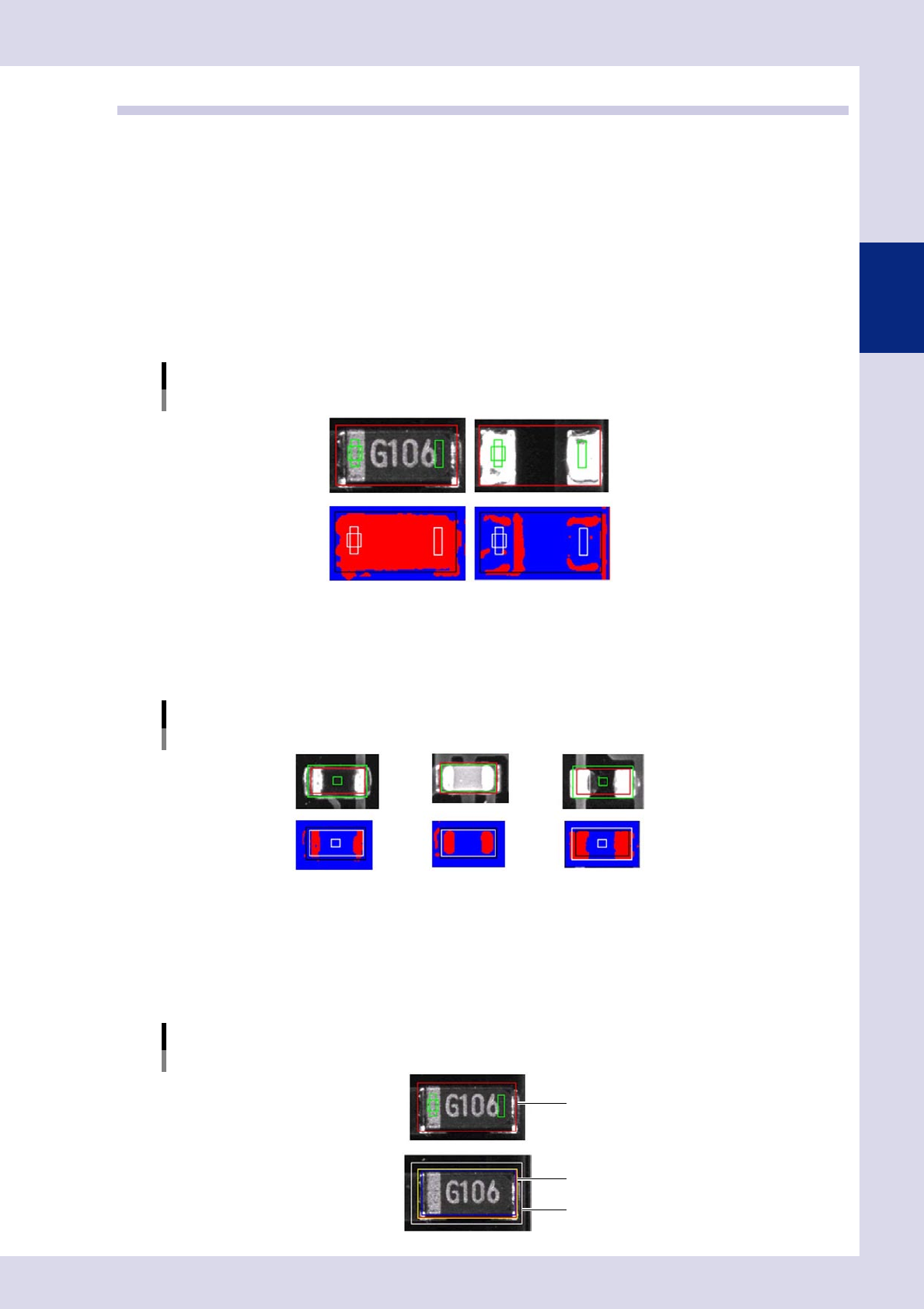
Parts check
This inspection mode detects the outer shape and body of a part, and determines whether the part is present or not
based on the detected area and size of the part.
Parts check
OK part Missing part
23205-P6-00
•
Electrode check
The inspection mode detects the electrodes of a chip part, and determines whether the part is present or not based
on the electrode pitch. Used primarily for chip resistors and chip capacitors.
Electrode check
Resistor Capacitor Missing part
23206-P6-00
n
Position deviation
•
Shift tolerance
An NG is judged if the detection area exceeds the allowable position displacement amount from the inspection frame
(step frame).
Shift tolerance
Inspection frame (step frame)
Inspection frame (step frame)
Permissible position deviation range
(Shift Tolerance)
23207-P6-00
2-6
2
Inspection data creation and tuning
n
Polarity
One of 3 inspection modes is used, depending on the part type.
•
Polarity check
This inspection mode detects the polarity mark on a part, and determines the polarity based on the area and size of
the mark.
•
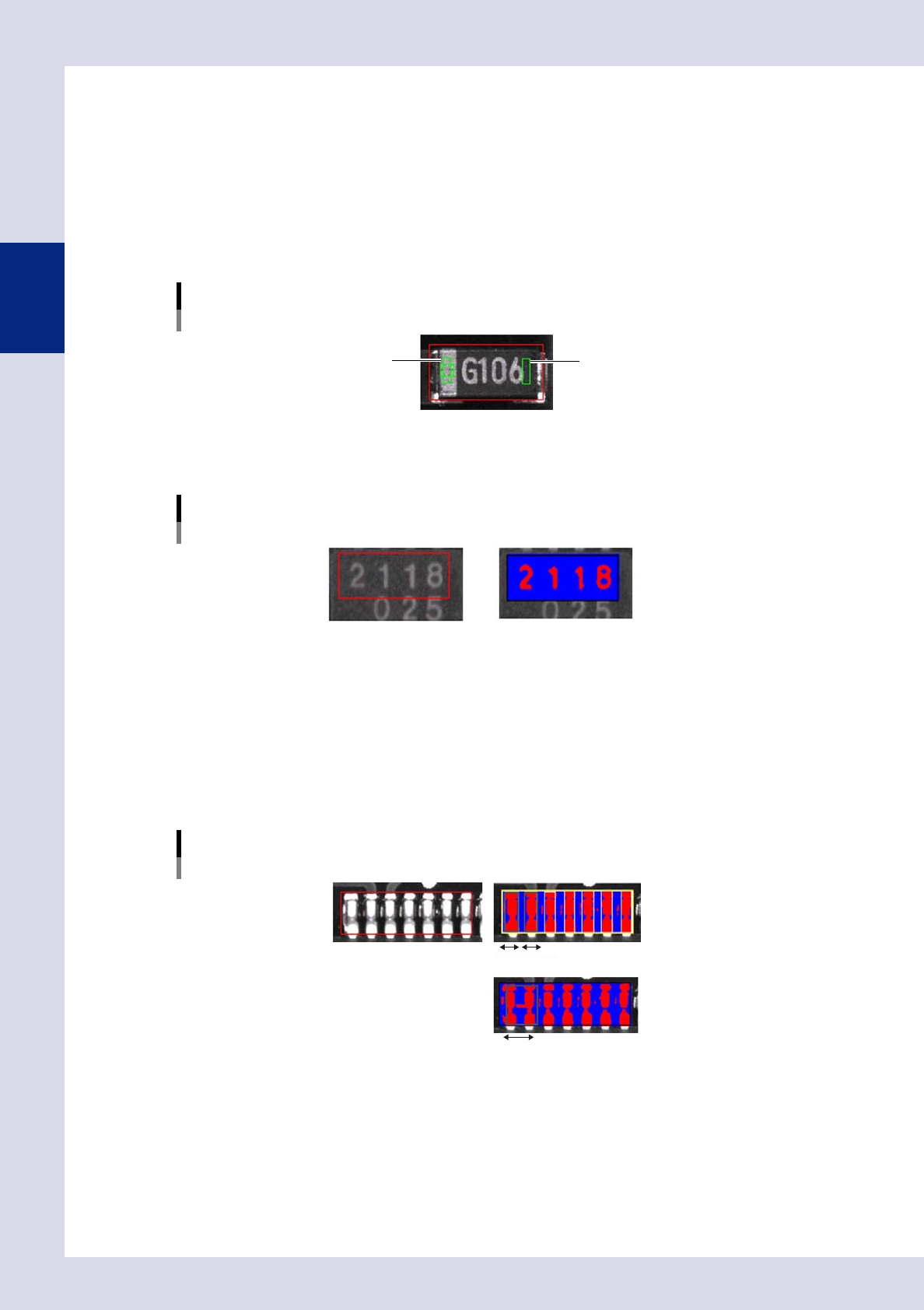
Comparison
This inspection mode subtracts the brightness level of one location from that of another location on a part, and
determines the polarity based on the result.
Comparison
1
2
23208-P6-00
•
Character recognition
Characters are detected, and judgment is made based on the character angle.
Character recognition
23209-P6-00
n
Bridge
•
Lead Check
One of 3 inspections modes is used, depending on the inspection location. It is recommended to test at the maximum
allowable size.
1. Maximum Acceptable Size
This is used for the inspection of bridges between leads on IC parts and so on.
Individual leads and solder inside the inspection frame are detected, and judgment is made based on the vertical and
horizontal sizes.
Maximum Acceptable Size
OK part
Bridge
23210-P6-00
2. Area
This parameter is used to detect the area of each lead to determine whether a solder bridge is formed between leads.
3. Pin Count (Lead Count)
This parameter is used for bridge inspections between leads of 3-pin and 5-pin transistors, etc.