YSI_Prog_E.pdf - 第65页
1-30 1 asic operation 2.2.3 Upside down automatic inspection settings T his section describes the settings required for upside down automatic inspection. In this description, the board surface inspected first is the up…
1-29
1
asic operation
2.2.2 Starting automatic inspection
1
Check the inspection program.
Check the inspection program name displayed in the "Status" area of the screen.
2
Press the [Auto] button in the "Button" area.
The "Auto inspection" screen opens to enter automatic inspection mode.
3
Set the board.
1. Align the conveyor width with the board.
2. Press the [Change] button. Set the board on the conveyor with the surface to be inspected first
facing up.
4
Press the [Execute] button to start inspection.
The safety cover opens when inspection is complete, and the subsequent inspection program is auto-
matically loaded.
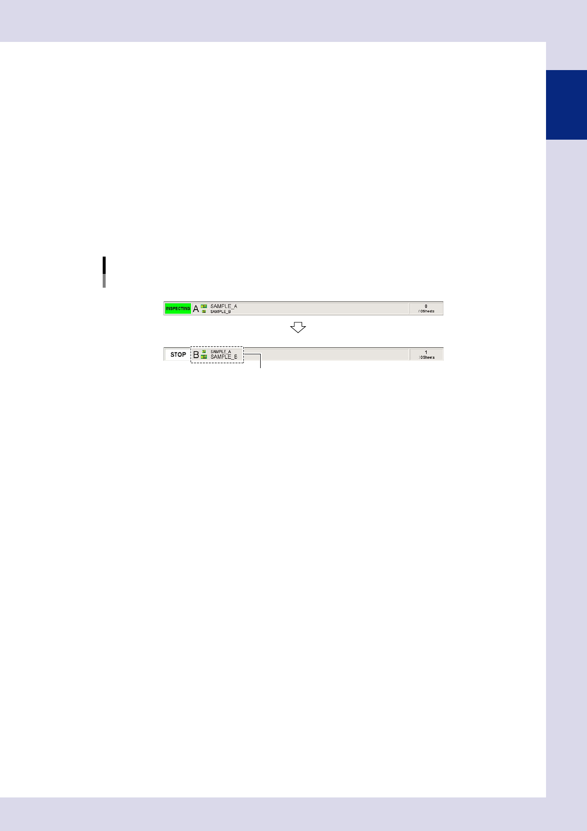
Inspection program switching
During first surface (A surface) inspection
After completion of first surface (A surface) inspection
Subsequent (B surface) inspection program is loaded.
24129-P6-00
5
Set the board with the upper and lower surfaces reversed.
Unload the board, and then set it on the conveyor with the completed surface facing down.
6
Press the [Execute] button to start inspection.
When the safety cover opens after inspection is complete, remove the board.
7
Inspect the next board.
Repeat the procedure in steps 3 to 6.
1-30
1
asic operation
2.2.3 Upside down automatic inspection settings
This section describes the settings required for upside down automatic inspection.
In this description, the board surface inspected first is the upper surface (Side A), and the subsequently inspect-
ed surface is the lower surface (Side B).
n
NOTE
• Ifperformingupsidedownautomaticinspection,select"Yes"for"InstallationSetting"
→
"Upside down inspection" in
the machine settings.
• Administratorprivilegesarerequiredtochangemachinesettings.
1
Load the program for the upper surface.
Open the "Setup" screen, and then load the upper surface program from the inspection program list.
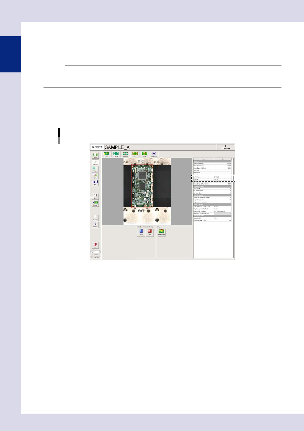
2
Open the [Data Edit] - [Board] screen.
Set the following parameters.
Board parameter settings
Upper surface (Side A)
[Save] button
24130-P6-00
ASSY Name
Enter an arbitrary name.
A/B Side
Select "Side A".
3
Press the [Save] button to save the settings.
1-31
1
asic operation
4
Load the program for the lower surface.
Open the "Setup" screen, and then load the lower surface program from the inspection program list.
5
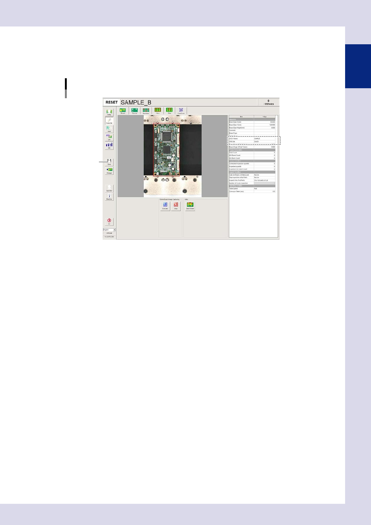
Open the [Data Edit] - [Board] screen.
Set the following parameters.
Board parameter settings
Lower surface (Side B)
[Save] button
24131-P6-00
ASSY Name
Enter the same ASSY Name as that entered for the upper surface.
A/B Side
Select "Side B".
6
Press the [Save] button to save the settings.