YSI_Prog_E.pdf - 第86页
2-15 2 Creating inspection pr ograms 2.4 Fiducial function Based on the recognized position results of fiducial marks allocated to boards, the fiducial function corrects errors that ma y occur from errors in machining th…
2-14
2
Creating inspection programs
Item Description
4 Inspect
Condition
Auto Lib Deploy at Data
Load
If "Use" is selected, libraries are automatically deployed when the
inspection program is loaded.
Skip Inspection of No
Parts
If "Use" is selected, when the result of the parts check or electrode
check when performing automatic inspection is NG, inspection of
identical parts is skipped, and the next part is inspected.
Inspect Only First Parts
"Inspect Only First Parts" or "?Inspect for Each Specified Qty" can be
selected when the inspection status is "Character recognition" or
"Polarity check". Inspection is not performed for other than the specified
board. Setting is required in the "Option" tab for each step.
Number of Cycle
Inspection
This is valid if "Inspect Only First Parts" is set for "?Each Specified
Qty?". Enter the cycle quantity for boards to be inspected.
5 Operating
Condition
Pass Mode Boards are transferred without performing inspection.
Table Speed
This should normally be set to "Fast".
However, set to "Slow" for heavy boards.
Conveyor Tiner (sec)
Sets the length of time that the conveyor is rotated after the board
unloading sensor confirms that the board has been unloaded.
6 X-Ray
X-Ray Mode
Selects whether to set the X-ray inspection settings in "Board Unit" or
"View Unit".
If "Board Unit" is selected, select the "View zoom".
View zoom
This is valid if "Board Unit" is selected for "X-Ray Mode".
Select a suitable magnification for inspection from the drop-down list.
Max Parts Height (mm)
Enter the maximum height of parts mounted on the board subject to
inspection.
2-15
2
Creating inspection programs
2.4 Fiducial function
Based on the recognized position results of fiducial marks allocated to boards, the fiducial function corrects
errors that may occur from errors in machining the board outline or from the board clamping mechanism, as
well as board warp. This function is used to correct the position of the entire board by registering fiducial
marks in the lower left (or upper left) of the board as Mark 1, and marks in the upper right (or lower right) as
Mark 2. (Up to three marks can be registered.) If required, register block fiducials or local fiducials after
registering board fiducial marks.
Board fiducial mark example
Board
Mark 2
Mark 1
Mark 3
(Register if necessary)
23213-P6-00
n
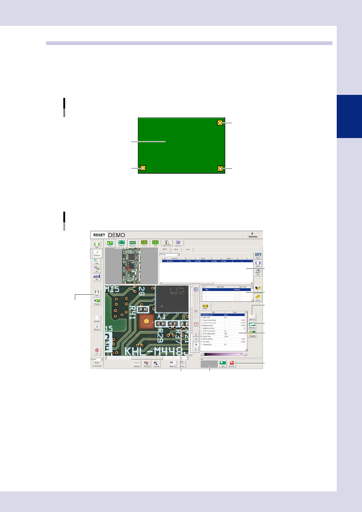
Fiducial screen
By pressing the [Data Edit] button and opening the "Fiducial" tab, the following fiducial mark setting screen appears.
[Fiducial] tab screen
Basic parameters
[Measure] button
[End Test] button
Threshold slide bar Recognition results
[Save] button
[Light List] button
Mark list
Mark data list
24210-P6-00
2-16
2
Creating inspection programs
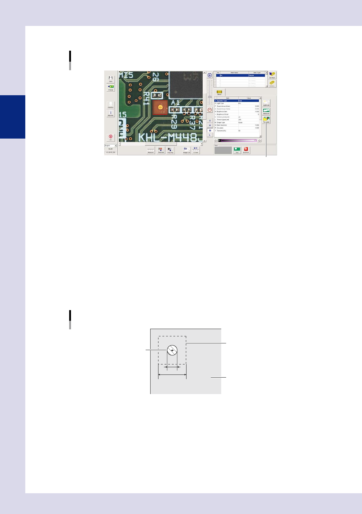
2.4.1 Basic parameters
Basic parameters
[Template] button
24211-P6-00
A. Algorithm Type
The algorithm type is selected from the following three types. "Form" should normally be selected.
If "Pattern Matching" is set, press the [Template] button, open the [Register Template] screen, and register marks in a
template.
• Pattern Matching
Recognizes the mark based on how closely it matches the image template.
• Form
Recognizes the mark based on the "Surface Type", "Std. Area", Mark Size XY", "Circularity", and "Perimeter" parameters.
• Edge
Recognizes the mark based on the "Surface Type" and "Mark Size" parameters.
D. Light Type
Selects the lighting used to recognize the mark.
F, G. Search Area X, Y (mm)
Sets the size of the area in which to search for the mark. Set the mark outline +3.00 mm as a guideline. For example, if
the mark outline is 1 mm as shown below, enter 4 mm. However, if there is a possibility that patterns (resist, silk, etc.)
other than marks may also be detected, narrow the mark detection range value so that only the mark is detected.
1
4
Mark detection range
Mark
Board
Mark detection range example
23214-P6-00
H. Brightness Gain
Adjust this value to brighten the entire image so that the mark is easily recognized.
I. Brightness Offset
Adjust this value to make the entire image darker so that the mark is enhanced.
K. Thresh Lower Limit, L. Thresh Upper Limit
Sets the upper and lower threshold limits for the brightness with which the mark is shown in red when performing mark
recognition.