KE2040Instruction Manual Ver2.01,REV04.2003.6.25.pdf - 第18页
1 − 1 CHA PTER 1 GENERA L 1.1 Highlights and Specifications This machine is an SMD chip shooter desig ned as one of t he KE-2000 series product s which are successors of t he KE-700 series chip placers, and f eatur es hi…
VI
Matters of Caution for Safe Use of
KE-2040M/KE-2040L/KE-2040E
DANGER
1. To prevent accidents due to electric shock, do not open the
electrical equipment box while power supply is on.
2. To prevent electric shock, do not operate the machine, with the
grounding line unlinked.
CAUTION
1. To prevent damage to human bodies, do not operate the
machine, with the safety cover or equipment removed.
2.
To prevent damage to human bodies, make sure that hair,
clothes, etc., will not be caught by the conveyor chain.
Also, keep off gloves.
3.
To prevent damage to human bodies, turn off power supply
during maintenance (greasing, adjustment, and daily
inspection).
4. To prevent damage to human bodies, use an earth leakage
breaker for the power line.
CAUTION
1. Windows NT (including the Ethernet communication function) is
adopted as the Operating System of this machine.
If you install on this machine any software not designed for this
machine, we cannot guarantee that the machine functions
properly. if you move, rename or copy a file stored in the
hard disk drive, we cannot guarantee that either.
•
Should the machine not properly due to any operation above,
replace your hard disk drive with new one and your data may
be lost.
CAUTION
1. A UPS is incorporated into this machine to protect a production
program and any other data at power failure.
To prevent a battery built into the UPS from degrading, do not
leave this machine without turning it on for six months or longer.
•
Only when the main circuit breaker and main switch are set
to ON, this machine is assumed to be turned on.
1 − 1
CHAPTER 1 GENERAL
1.1 Highlights and Specifications
This machine is an SMD chip shooter designed as one of the KE-2000 series products
which are successors of the KE-700 series chip placers, and features high-speed chip
placement.
A host line computer (HLC) controls a line consisting the KE-2000 series chip
placer/shooter, KE-700 series chip placer, JUKI dispenser and solder-paste printer as
well as a line consisting of KE-2000 series chip placers/shooters only. This feature
allows you to configure a line which realizes high productivity and is appropriate for
every applications.
For software, WindowsNT is adopted as the Operating System (OS) to increase the
operability of this machine.
1.1.1 Highlights
– Equipped with the newly developed laser alignment sensors (MNLA) each of which
allows four nozzles to recognize components simultaneously. These four nozzles
simultaneously pick up and mount components whose size is up to 10 mm x 10 mm
after centering them without touching: this allows high-speed mounting of
components, 11,000 cph (this is rough estimate calculated on the assumption that four
components are simultaneously picked up, then one component is alternatively placed
on the almost entire area of a 330 mm x 250 mm board).
(applicable to a KE-2010 or KE-2020)
– Equipped with the new component recognition system composed of the various
lighting functions: reflective/penetrative lights switching function, three-dimension
movable light, illuminance control, waveform (color) switching function, and coaxial
light. This system improves the recognition capability of components such as a QFP,
BGA, CSP and irregular-shaped components such as a connector.
– Provided with three camera options as well as the standard component recognition
camera (which shoots up to a 50 mm x 50 mm component): it allows you to select a
camera appropriate to each component.
– An offset correction camera, a height measurement device (option), and a feeder
preparation function (option) can be installed to minimize the time required for the
machine halt for preparation, realizing high operating ratio.
– An offset camera correction uses its pattern matching function to recognize a fiducial
mark at high speed. Together with high-speed board transfer, it provides you with an
overall high-speed placement capability.
– Its twin FMLA high-resolution head and twin image recognition camera unit enable
images of two components to be recognized at the same time (applicable to a
KE-2040).
– Pick and placement reliability is remarkably improved through chip rise detection
performed during laser/align measurement.
– The board support section (for backing up a board) is driven by a motor to prevent any
vibration from occurring when a clamped board is released, then prevent a placed
component from being shifted from the regulated position, shortening the time required
to clamp or release a board.
– Using the offset correction camera and the height measurement device, preparation is
possible without opening the cover, provided as good safety features.
– Newly attached LED indicators (optional) (Feeder Position Indicator: FPI) on the feeder
setting section notify an operator that components run out, and generates the warning
on the number of the remaining components to increase the operability for replacing
components.
– WindowsNT increases the operability of the machine greatly.
1 − 2
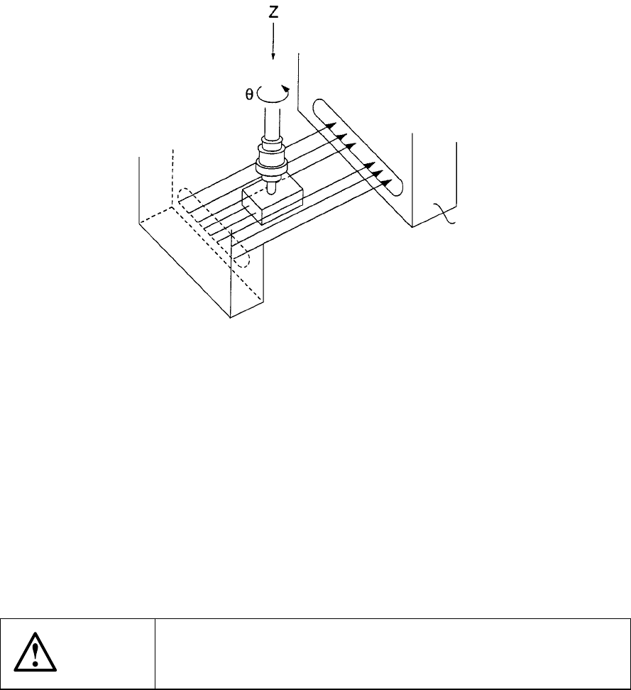
1.1.2 Centering system
Instead of using conventional mechanical centering system, this machine uses
touchless centering system where laser align sensor is used to read the position and
angle of components. This can be achieved by detecting the shade of the
components created by the laser rays applied horizontally to the components.
Figure 1.1.2.1 FMLA
By moving Z-axis up and down, a component is picked with vacuum, and the laser is
applied to the component. A shade is made where the laser is obstructed by the
component. By turning the component along q-axis, the shade changes.
According to the change of the shade, offsets of the position and angle of the picked
component are calculated. These offsets are corrected when mounting.
The laser align sensor conforms to IEC825 Class 1 and CDRH Class 1 regulations.
The laser align sensor can be used safely as far as it is used by following the
instructions described in this manual.
CAUTION
Any operation of controls and adjustments which is not described in
this manual can cause an excessive exposure of laser lays which
may be dangerous to human bodies.
Laser align sensor