KE2040Instruction Manual Ver2.01,REV04.2003.6.25.pdf - 第439页
5 − 49 Af ter data is completed, press the OK but ton. The editing screen r eappears. T he fo llowing dialog is displayed by pressing “Component V iewer”. How to use “Component View er” is descr ibed in “5.2. 4.6 Compone…
5 − 48
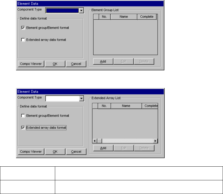
(1) Setting items
1) Select a component type from the “Component Type” combo box at first:
- Leaded Component
- Ball Component
- Outline Component
2) Define the data format.
Check either one of the corresponding check boxes for defining the data
format:
- Element group/Element format
- Extended array data format
▼ When you select “Element group/Element format”
▼ When you select “Extended array data format”
Element
group/Element format
Use this data format for a component whose elements are arranged regularly.
Extended array data
format
Use this data format for a component having an irregular ball pattern (available
only if you select “Ball Components” as the “Component Type”).
1) Editing data
- When you click the <Add> button, the detailed “Element Group” screen or
“Extended Array” screen appears which allows you to create new data.
- When you select an element group from the “Element Group List” and click
the <Edit> button, the detailed “Element Group” screen or “Extended Array”
screen appears in the same manner when you click the <Add> button to
allow you to edit the displayed data.
- When you select an element group from the “Element Group List” and click
the <Delete> button, the selected element group is deleted.
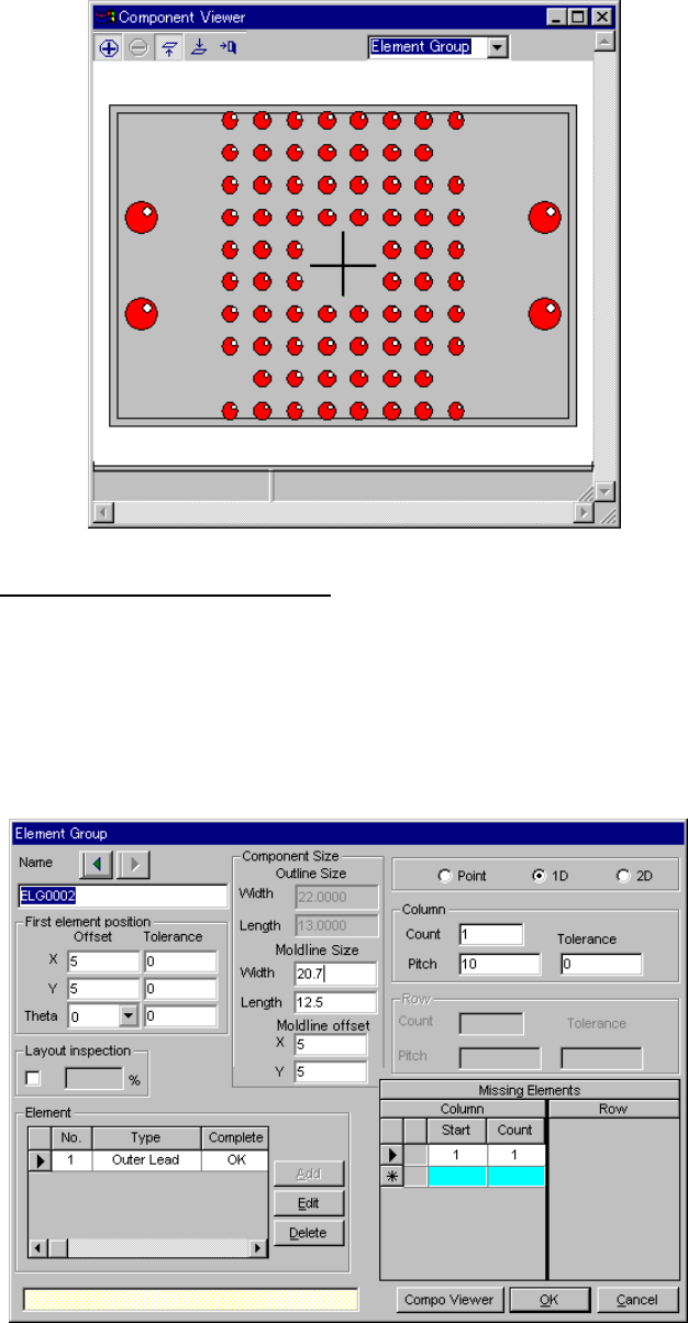
5 − 49
After data is completed, press the OK button. The editing screen reappears.
The following dialog is displayed by pressing “Component Viewer”. How to
use “Component Viewer” is described in “5.2.4.6 Component Viewer”.
3.1 Element group/Element format
This screen allows you to group components whose lead (ball) pitch, lead
length or ball diameter is the same as each other, and create or edit data
on a group.
- Up to 20 element groups can be defined.
- When you check the “Element group/Element format” check box and
click the <Add> or <Edit> button, the following screen appears.
5 − 50
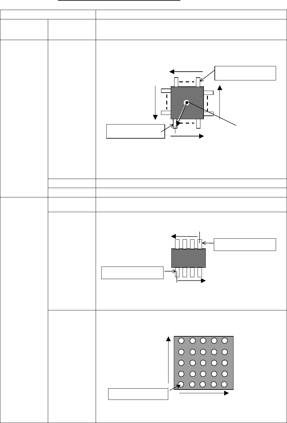
3-2. Detailed description of each setting item
Setting item Description
Element group Name Enter up to 32 alphanumeric characters to assign an element group name. You
can omit this setting item. When omitted, “ELGxxxx” is assigned to an element
group, where xxxx is a four-digit integer automatically obtained.
Offset
(X, Y, Z, Theta)
Enter the coordinate of the center (or ball center for a ball component) of the
reference lead (reference element) end with being viewed from the center of a
component.
Note that when you select “2D” as the “Dimension”, enter “0” to the “Theta” field.
You cannot enter any other value here. The center of a component is normally
that of the outline of the component.
Tolerance Enter the allowable offset coordinate range.
First element
position
Layout inspection Set the level used for checking an element layout error (default: 20 %).
Point (Side,
corner, mark)
Select this radio button if you set only one lead (ball) to be checked.
1D (lead) Select this radio button if you set leads arranged in a column to be checked.
Dimension
2D (Ball, Land) Select this radio button if you set leads (balls) arranged in a row and column to be
checked.
Center of a
component
Reference element
Reference element
Arrangement direction (0 degrees)
(90°)
(270°)
(180°)
Arrangement direction
Reference element
Arrangement direction
TOPVIEW
Reference element
Reference element
Arrangement direction of
arow
BOTTOMVIEW
Arrangement direction of
a column