KE2040Instruction Manual Ver2.01,REV04.2003.6.25.pdf - 第49页
1 − 32 3. Tape feeder parts identifi cation The tape f eeder uses a t ape whose w idth is 8 mm, 12 mm, 16 mm, 24 m m, or 32 mm to supply components. FF05/08 Parts identif ication ( 1/2) 12 11 10 16 4 17 6 5 1 2 14 19 15 …
1 − 31
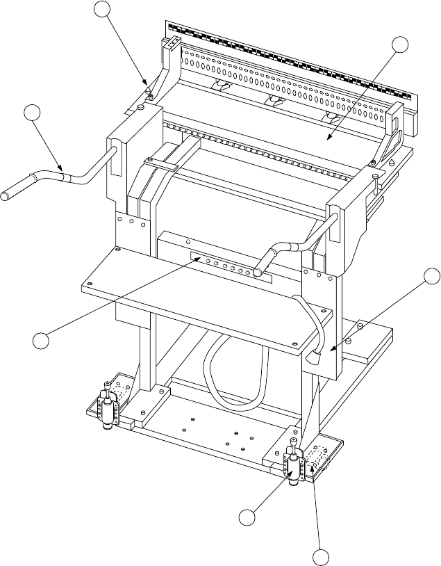
2. Overall feeder exchange trolley parts identification
(See Figure 1.2.3.3.) (Optional)
The Overall feeder exchange trolley is used to remove the feeder bank from the
main unit for easy preparation.
The feeder bank
①
can manually be moved by holding the trolley handle r which
is attached to the floor trolley
③
equipped with casters
②
. Positioning to the
main unit of this machine is carried out with the bank locate pins t on the left and
right. The Overall feeder exchange trolley can be fixed with the trolley stopper
⑥
.
2
1
5
4
7
3
6
①
Feeder bank
⑤
Bank locate pin
②
Casters
⑥
Trolly stopper
③
Floor trolley
⑦
Connector bracket
④
Trolly handle
Figure 1.2.3.3
1 − 32
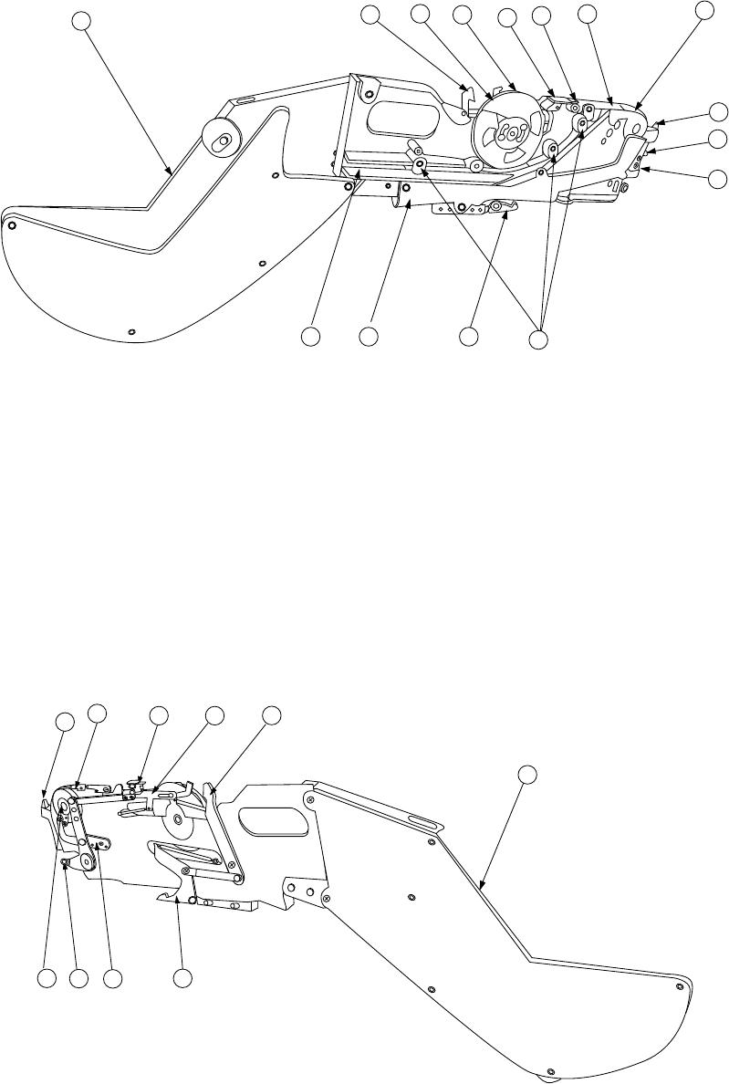
3. Tape feeder parts identification
The tape feeder uses a tape whose width is 8 mm, 12 mm, 16 mm, 24 mm, or 32
mm to supply components.
FF05/08 Parts identification (1/2)
12
11
10
16
4
17
6
5
1
2
14
19 15 13
18
Figure 1.2.3.4 Right side view
①
X axis reference pin A
⑧
Stopper
⑮
Guide cover
②
X axis reference pin B
⑨
Free link
⑯
Unreeling plate
③
Sprocket wheel
⑩
Tape holder
⑰
Unreeling guide roller
④
Upper cover
⑪
Cover tape fixing plate
⑱
Reel support
⑤
Upper cover hook
⑫
Lock release lever
⑲
Tape groove
⑥
Shutter
⑬
Lock holder
⑦
Knock lever
⑭
Tape guide
18
12
9
4
5
16
8
7
3 13
Figure 1.2.3.5 Left side view
1 − 33
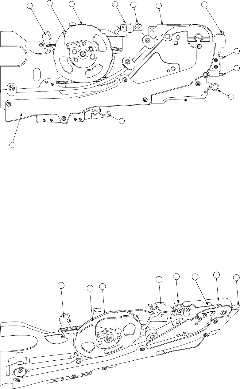
FF05/08 Parts identification (2/2)
12
11
16
17
4
5
15
13
7
2
1
10
Figure 1.2.3.6 Detailed illustration of the right side
①
X axis reference pin A
⑧
Stopper
⑮
Guide cover
②
X axis reference pin B
⑨
Free link
⑯
Unreeling plate
③
Sprocket wheel
⑩
Tape holder
⑰
Unreeling guide roller
④
Upper cover
⑪
Cover tape fixing plate
⑱
Reel support
⑤
Upper cover hook
⑫
Lock release lever
⑲
Tape groove
⑥
Shutter
⑬
Lock holder
⑦
Knock lever
⑭
Tape guide
12
11
10
16
17
5
6
4
Figure 1.2.3.7 Detailed illustration of the top side